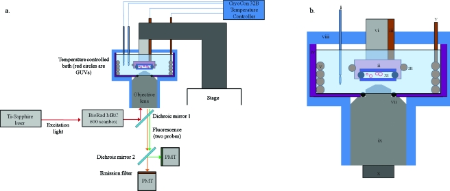
Figure 1.
(a) Block diagram of the imaging apparatus. 780 nm excitation light (red arrow) from a Ti:sapphire laser is routed to a Bio-Rad MRC600 scanbox, which raster scans the beam through the objective lens and across the sample. The sample consists of an aqueous suspension of GUVs (red circles) between two glass coverslips (dark blue) and sealed from the bath water by clear nail polish and Fomblin perfluorinated vacuum grease. The entire sample and part of the objective lens are contained within the sample bath and submerged in water as shown. Two heaters (orange) and two RTD thermometers (one for each heater) are connected to the CryCon model 32B temperature controller, which is remotely operated by an RS232 connection to a PC. The excitation light is separated from the fluorescence light (orange and green arrows, denoting two different fluorophores) by dichroic mirror 1, and the fluorescence emissions are then separated by color by dichroic mirror 2 before being collected by the PMTs. (b) Close-up of the sample bath. The components are labeled i–xi: (i) Pt100 RTD, (ii) copper sample holder, (iii) small (loop 2) cable immersion heater, (iv) Teflon cup (purple), (v) large (loop 1) bath water heater, (vi) Teflon rod for the sample holder, (vii) o-ring seal (black) between objective lens and Teflon cup, (viii) foam insulation (blue), (ix) objective lens (UPlan Apochromat 60×, Olympus), (x) thermal isolator for objective lens, and (xi) GUV (red circles) samples between two round coverslips (dark blue).

