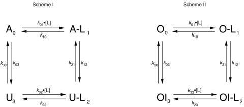
Figure 1. Simplified gating schemes describing the putative actions of H+ or Ni2+ ions on Kv1.5 channels at resting and depolarized potentials.

First order rate constants are shown as kxy, where x and y denote the states (identified by the subscripts 0, 1, 2 or 3) involved in the transition. The concentration of H+ or Ni2+ ions, also known as the ligand, is shown as [L]; L denotes a ligand-bound state. Scheme I: at rest (−80 mV) channels in the upper row are in the available (A or A-L) state and able to pass current during test depolarizations to +50 mV. Channels in the lower row are in the unavailable or resting inactivated state (U or U-L) and remain non-conductive during test depolarizations. Resting inactivation is defined as the transition at −80 mV from the A to U state or from the A-L to U-L state. See Methods for details. Scheme II: at +50 mV channels are either in the open (O or O-L) and conducting state or in the open-but-slow-inactivated (OI or OI-L) and non-conducting state. Slow inactivation is defined as the transition at +50 mV from the O to OI state, while H+- or Ni2+-enhanced slow inactivation is defined as the transition from the O-L to OI-L state. See Methods for details.
