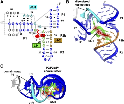
FIGURE 1.
Structure of the SAH aptamer. (A) The secondary structure of the modified sequence of the Rso SAH riboswitch is shown with paired regions P1, P2, and P4 (blue), joining region J4/2 (orange), J2/1 (green), and J1/4 (cyan). The SAH ligand is depicted as a red icon and nucleotides that are disordered or involved in a domain swap are colored gray. Base interactions are represented using the notation of Leontis and Westhof (2001). (B) Cartoon representation of the aptamer tertiary architecture is shown with the color scheme used in A. SAH is shown in red and the dots represent the van der Waals surface of SAH. Gray dots depict nucleotides that could not be modeled into the electron density map. (C) The tertiary structure from B rotated 90° to emphasize that the adenine ring from SAH participates in the P2/P4 coaxial stack.

