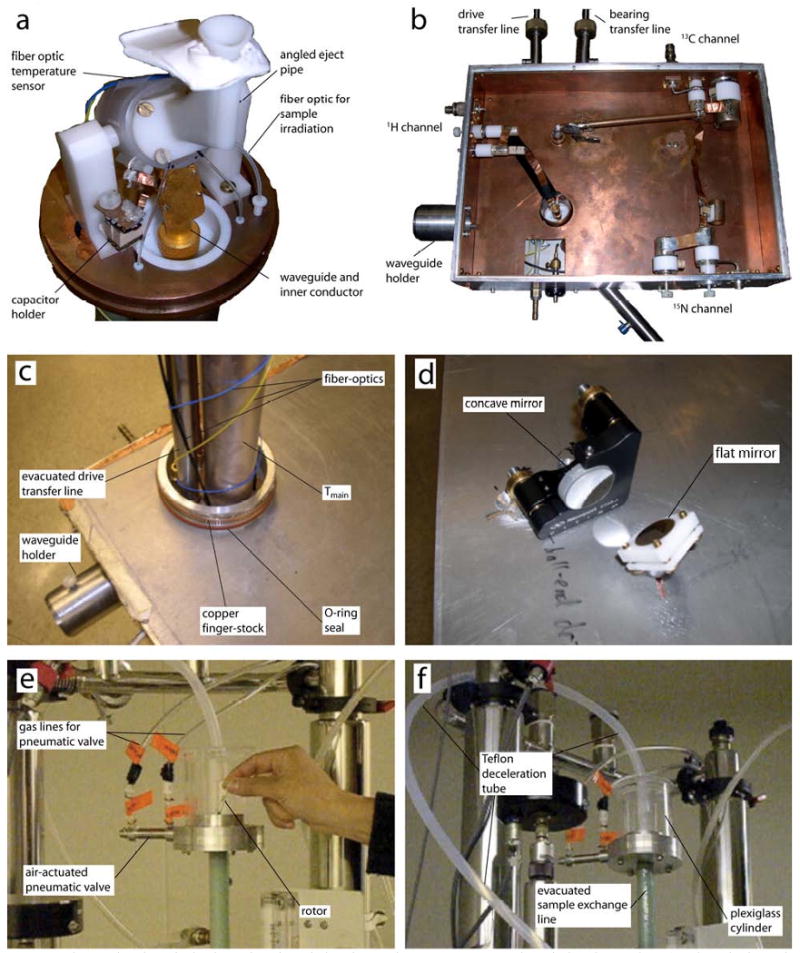
Fig. A1. Appendix. Photographs of instrument.

a) Photograph of the probe. b) The inside of the probe box showing the RF circuit. c) Top of the probe-box showing the seals to the probe-dewar. d) Mirrors on the bottom plate of the probe-box for coupling microwaves from the horizontal waveguide to the vertical waveguide e) Sample insertion chamber at the top of the magnet f) Deceleration tube that gently stops the rotor during the ejection process.
