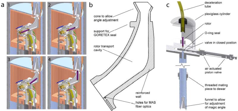
Fig. 5.

Sample ejection schematics a) Cut-away of probe showing the rotor (purple). A burst of nitrogen gas into the exhaust port creates a flow of gas out of the probe and into the vacuum-jacketed sample exchange tube, carrying the rotor from the stator (1) into the angled sample eject pipe (1 and 2) and finally into the vertical exchange tube (4). For sample insertion, the rotor is lowered on a cushion of gas from the top of magnet and follows the reverse path. b) Angled sample eject pipe. The rotor exits the stator and is guided by the bottom surface of the eject pipe to make the turn from 54.5° to 0° with respect to the magnet bore axis in the limited space provided. The top of the eject pipe is a cone which fits inside the larger cone of the vertical eject tube to allow for adjustment of the magic angle. c) Vertical sample exchange tube. A threaded aluminum attachment allows for a secure coupling into the probe-dewar and proper alignment of tube with respect to the cone on the sample eject pipe. A custom designed valve is closed during operation to prevent frost formation, and is remotely opened during sample exchange. For ejection the rotor travels into a ½″ Teflon tube which coils around to slowly and safely slow the rotor.
