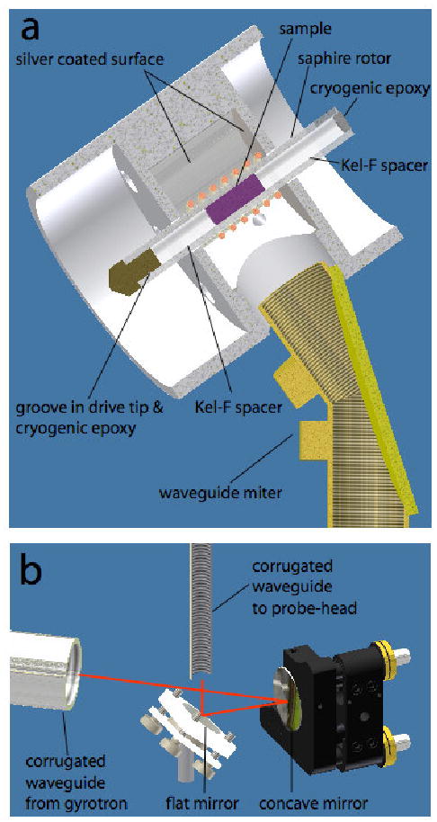
Fig. 6.

250 GHz microwave channel and rotor details. a) Enlarged view of the probe with selected components shown. A small groove in the vespel drive-tip is filled with a cryogenic epoxy, Hysol EA 9361 (Loctite) to prevent the drive-tip from coming loose at cryogenic temperatures. The epoxy is also used to seal the top of the rotor. The top Kel-F spacer is threaded, providing a simple and safe way to empty and fill the rotor; the epoxy can be removed with a standard epoxy-stripper, while a 0-80 threaded tool threads into the top spacer, providing a grip to pull the spacer out of the rotor. The microwave power is coupled from the HE11 mode of the corrugated waveguide to the sample by launching the microwaves from the waveguide in the form of a free space propagating Gaussian beam. b) a system of mirrors inside the probe-box focuses the beam delivered by the horizontal corrugated waveguide from the gyrotron onto the vertical waveguide leading to the sample. The red lines trace the trajectory of the microwaves.
