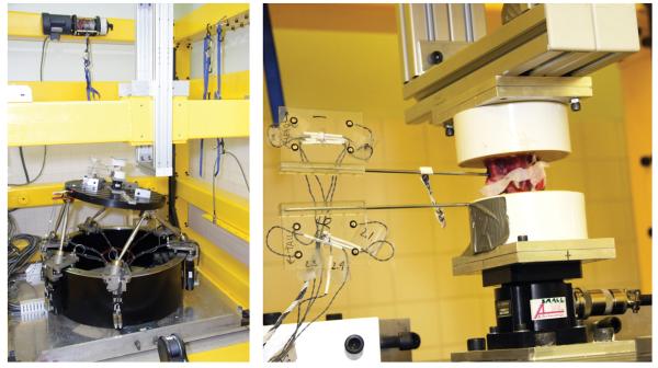
Figure 2.
The left image displays the parallel robot with a potted motion segment attached to the robot's active surface. The motion segment has yet to have its most cranial end (i.e. vertical in this orientation) attached to the rigid cross beam that has been moved into the foreground. The image on the right is a close up view of the potted segment. The caudal end of the specimen is connected to a 6 axis load cell that is then connected rigidly to the robot below. The cranial end of the segment is now attached rigidly to the cross beam located above the sample.

