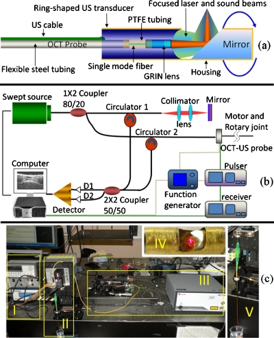
Figure 1.
Schematic of US-OCT probe (a) and imaging system (b). Photograph of the US-OCT system (c); I, US subsystem; II, motor and rotary joint device; III, OCT subsystem; IV, close-up of the hybrid probe (visible light was used here for photograph); and V, close-up of the probe assembled to rotary joint device.

