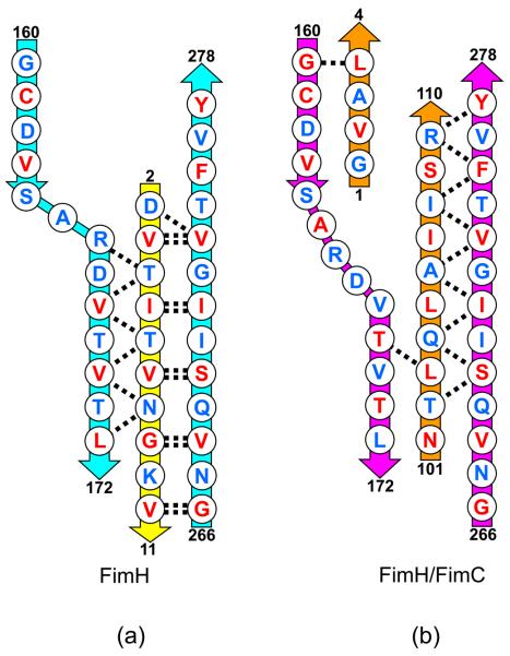
Figure 5.
Schematic diagram showing the alignment of the polypeptide chains. (a) FimH (cyan) in complex with FimG donor strand (yellow). Main chain hydrogen bonds shown as dashed lines. Residues with side chains pointing towards the center of the domain shown in red. Residues pointing away from the center shown in blue. Residue numbers shown for ends of each polypeptide segment. (b) FimH (magenta) in complex with FimC (orange). Hydrogen bonds and side chain orientations as in (a).

