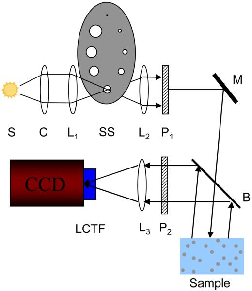
Figure. 1.
Schematic of LEBS experimental instrument. A broadbaned 450 W Xenon source (S) is imaged onto an aperture of variable size which serves as a secondary source (SS). The size of the aperture is selected by appropriately positioning the aperture wheel. The beam is collimated with lens L2 and passed through polarizer P1. A beam splitter (B) allows collection of backscattered light from the sample. The co-polarized light is selected with polarized P2. Lens L3 then maps the angular distribution of the backscattered light onto the CCD camera detection chip. A liquid crystal tunable filter (LCTF) attached to the camera is used to select the wavelength of collection.

