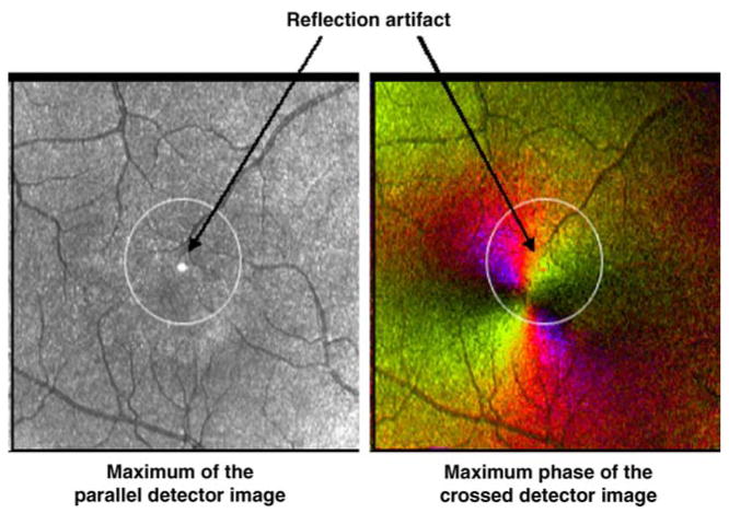
Figure 3.
A 5 deg, movable circle was available for the grader to define a central region based on vessel and contrast features, and the grader then selected a single foveal location within that circle. The Maximum of the Parallel Detector Image and Maximum Phase of the Crossed Detector Image are displayed here with the circle in the initial position prior to grader manipulation. There is a reflection artifact located in the center of each image that is the result of a reflection in the GDx.

