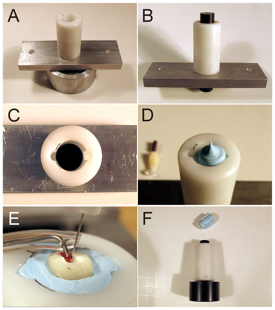
Fig.2.
Photographic images of the simulated closed-end fixture employed in the present study. A. The closed canal fixture assembled from its component parts. A Teflon spacer is attached via a metal base to a circular base holder for attachment to the experimental fluid delivery and suction system (see Fig. 3). B. A (black) spacer is inserted into the Teflon holder. C. The spacer is pushed to the bottom of the holder to serve as the base to prevent extrusion of the polyvinylsiloxane impression material from the bottom of the fixture. Two anti-rotation grooves prevent rotation of the set impression material within the holder during canal cleaning and shaping procedures. D. The Teflon holder is filled to the top with impression material. The root is inserted into the impression material before it sets. E. A groove (marked red) is placed on one side of the canal wall dentine to facilitate fitting of the master suction tip. F. After completion of the canal shaping and irrigation procedures, the polyvinylsiloxane impression material is displaced from the Teflon holder with a cap screw for retrieval of the root.

