
Figure 1.
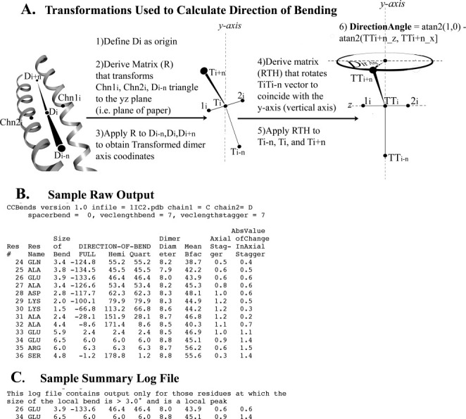
Direction of bending calculation and output files of CCBENDS. A: The indicated transformations facilitate calculation of the fully signed bending direction angle of a parallel dimeric alpha-helical coiled coil axis using the atan2 function. Value of 0° indicates bending of the axis within the local plane towards chain 1, ±180° indicate in-plane bending towards chain 2, ±90° indicate out-of-plane bending, and ±45° or ±135° indicate diagonal bending (see also Table SI in Supporting Information). The example schematic shown in this figure displays a direction of bending of c. +70°, nearly out of the plane of the local dimer. (Note that the chain axis at each residue is calculated using the coordinates of the nearest five alpha-carbons, and the dimer axis is the simple average of the chain axes.) B: Sample raw output file includes fully signed and symmetry-reduced (“hemi” or “quart”) local bend direction angles, as well as other coiled-coil parameters for each residue (See Methods for explanations). C: Corresponding summary file extracts from the raw output file those residues at which the size of the bend is both >3.0° and is a local peak, that is, greater than that of the prior and subsequent residue. [In this example, the fully signed measurement shows that the two local bends, which bracket an axially staggered stretch, are oppositely signed (i.e., closer to 180° apart than 0° apart), which is a signature of this (near) in-plane bending design. Such pairs of nearly oppositely signed near-in-plane local bending angles also surround three other axially staggered alanine clusters in tropomyosin as well as axially staggered clusters of bulky core residues in myosin. See also Fig. 3.]