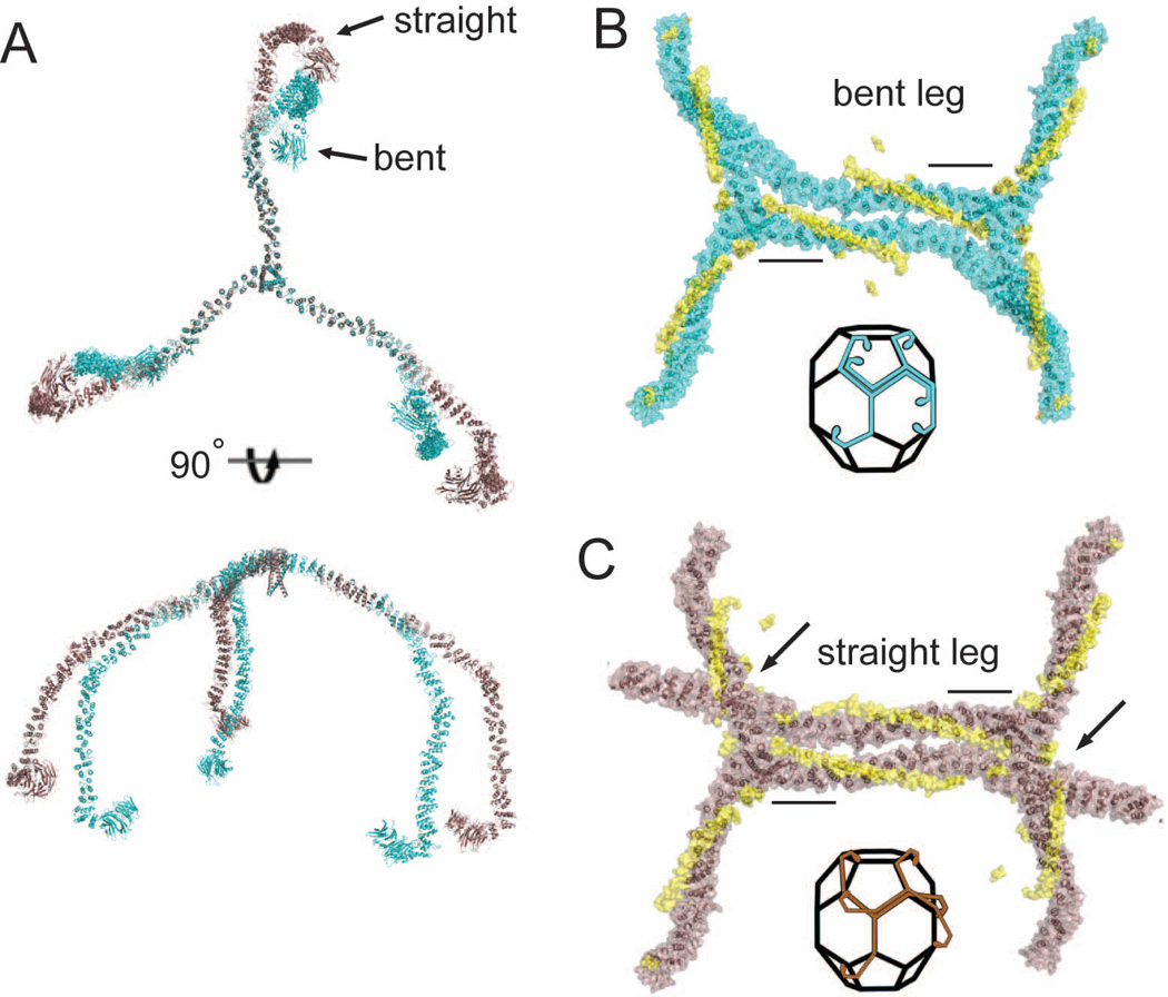
Figure 3. Modeling clathrin light chain-induced conformational changes in the triskelion knee and comparison to the assembled clathrin lattice.
(A) Clathrin heavy chain triskelia with all straight knees or all bent knees were modeled by alignment of distal legs (residues 1–1130) from the cryoEM structure of Fotin et al. (2004) with the hub structures determined here. Straight conformation (brown) and bent conformation (cyan) of knee regions are shifted ~30° starting from the KR loop hinge point. (B and C) Alignment of two modeled hubs, both with a single full length bent knee leg (B) or straight knee leg (C), with two assembled triskelia in the cryoEM structure (Fotin et al., 2004)(1XI4). Black bars indicate regions used to align cryoEM and hub crystal structures and the clathrin light chains are shown in yellow in their relative positions in the hub-LCb complex. Arrows indicated point of steric clashes in C. Insets indicate the geometric alignment of the bent or straight leg triskelia as modeled in (A) along edges of the clathrin basket.

