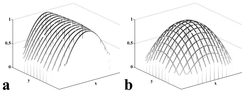
Figure 1.
Calculated gradient lines. (a) A set of calculated gradient lines after curve fitting in the x-direction. All of the gradient lines are scaled such that their maximum equals unity. (b) After multiplying by scaling factors, the combination of x- and y-gradient lines form a gradient mesh. The scaling factors are computed by minimizing the least square differences between the x- and y-gradient lines at the intersections.

