
FIG. 1.
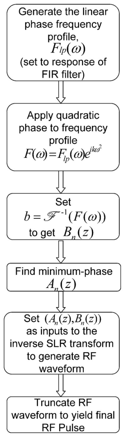
Flowchart illustrating main steps in the adiabatic SLR algorithm. The linear phase spectral profile is set to be the Fourier transform of a FIR filter produced by the firls function in MAT-LAB. Quadratic phase is overlaid on the linear phase profile. The coefficients b for the Bn (z) polynomial are set to the Fourier transform of the final spectral profile. A minimum-phase An (z) polynomial is calculated. Once An (z) and Bn (z) are specified, they are set as inputs to the inverse SLR transform and the output is truncated to produce the final RF pulse.