
Figure 2. Current structural status of the BK channel.
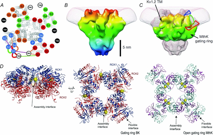
A, the transmembrane segments location using the cysteine cross-linking technique (Liu et al. 2008). Kv1.2/Kv2.1 chimera S1–S6 with superimposed, labelled circles, uniquely coloured for each subunit. TM1 and TM2 of β1 subunit are in white or black circles. B, BK 20 Å structure. BK structure resolved by electron cryomicroscopy at 20 Å shows a large protrusion at the periphery of the VSD, which has been suggested to correspond to the additional helix S0 and the extracellular 40 N-terminal residues of BK α-subunit. C, a view of the BK map (mesh) with Kv1.2 transmembrane region and MthK gating ring docked. The blue triangle and the red polygon indicate possible locations for the N-terminal region and the S0–S1 linker, respectively. The green oval is the proposed location of the S0 helix (Wang & Sigworth, 2009). D, left and centre panels, the BK gating ring solution at 6.0 Å. The centre panel is viewed down fourfold symmetry axis with RCK1 in blue and RCK2 in red. Calcium ions are shown as yellow spheres. Right panel, the open gating ring structure from the MthK channel viewed down the fourfold axis. Notice that a Ca2+ binds to the assembly interface in the BK gating ring whereas two Ca2+ ions bind to the flexible interface in the MthK gating ring (Yuan et al. 2010).