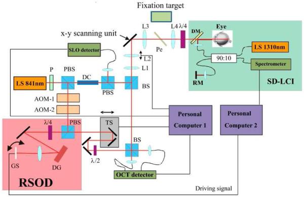
Fig. 1.
Scheme of the SLO/OCT instrument. RSOD rapid scanning optical delay line, SD-LCI spectral domain low coherence interferometer, LS light source, P polarizer, DC dispersion compensation glass rods, BS beam splitter, L1-L4 lenses (L1 f = 50mm, L2 f = 20mm, L3 f = 40mm, L4 f = 80mm), AOM acousto optic modulator, TS translation stage, PBS polarizing beam splitter, DM dichroic mirror, RM reference mirror, DG diffraction grating, Pe Pellicle, GS galvo scanner, x-y scanning unit consists of a resonant scanner and a galvo scanner. (Imaging optics between the two scanning mirrors are omitted for clarity)

