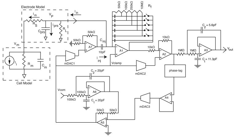
Figure 2.
One channel of the two-channel integrated patch-clamp system and the electrical model of a cell and pipette electrode. The main signal path is from the membrane current Iin to the monitor voltage output Vout = IinRf, through operational amplifiers A1, A2 and A3. Multiplying digital to analog converter mDAC 1 controls the parasitic capacitive compensation, mDAC 2 provides leak subtraction, mDAC 3 and the phase-lag controller circuit provides series resistance compensation. Input reconstruction and output anti-aliasing filters are also integrated. mDAC 1 and mDAC 2 are voltage-mode, R-2R DACs with R=50 kΩ, minimum gains of 0.5, and resolutions of 8 and 10 bits, respectively. mDAC 3 is a 9-bit hybrid transconductance-mode DAC with a maximum transconductance of 0.2 mS. Typical values of the electrode and cell elements are Cprs=5 pF, RL=100 MΩ, Rs=10 MΩ, Cm=30 pF, Rm=100 MΩ and peak values of Ii are 1-10 nA.

