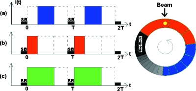
Figure 2.
A schematic illustration of the method for generating a type II field pair. The three beam pulse patterns differ in location and width, (a) covering only the lower right section of the modulator track, (b) the upper section, and (c) the sum of (a) and (b), covering both as in a conventional dose delivery. T is the rotational period of the modulator track and SB marks the position of the stop block.

