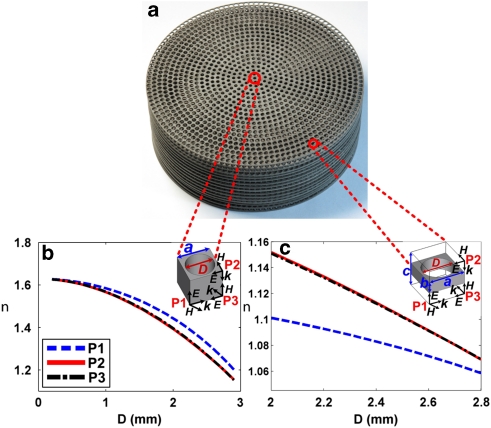
Figure 2. Unit cells used in the design of the cloak and the relation of geometry to electric field polarization.
(a) The designed ground-plane cloak. (b) The 3×3×3 mm3 drilled-hole unit cell, in which a=3 mm, and the relations between effective index of refraction and unit-cell geometry for different polarized incident electric fields at 10 GHz. P1, P2 and P3 are three orthogonal polarizations, E and H are the electric and magnetic field and k is the wave vector of the incident radiation. (c) The 3×3×1 mm3 drilled-hole unit cell, in which a=3 mm, b=3 mm and c=1 mm, and the relations between effective index of refraction and unit-cell geometry for different polarized incident electric fields at 10 GHz.

