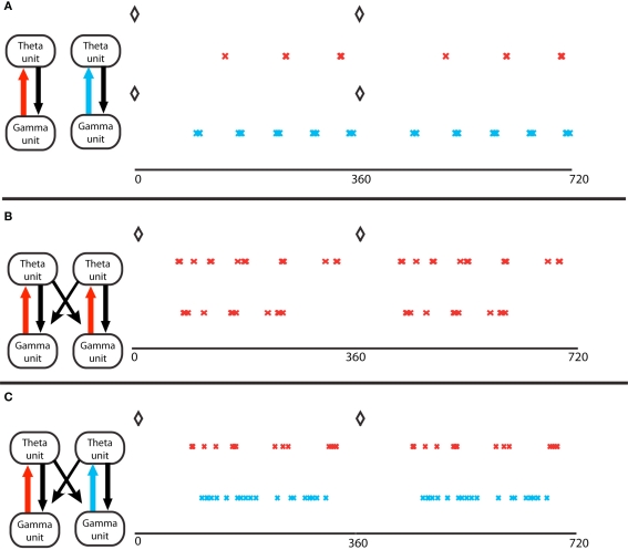
Figure 3.
Gamma assemblies prefer different theta phases depending on local synapses. (A) Theta phase of gamma spikes, for a single module. Top, a module in the excitation-dominated (ED) regime; red crosses mark the pyramidal cell spikes. The black diamonds mark the O-LM spikes at zero theta phase in all panels. Bottom, a single module in inhibition dominated (ID) regime; light blue crosses mark the pyramidal cell spikes. Theta phases of gamma spikes cluster more in ED regimes. (B) Two coupled modules, in identical ED regimes, receiving different gamma drives. The spike phases on top are for the pyramidal cell of the module that receives stronger gamma drive. The two cell assemblies do not synchronize (Tort et al., 2007). (C) Two coupled modules, receiving identical gamma drive, in different excitation regimes. The red crosses mark activity of the module in ED regime, the light blue marks report activity of the module in ID regime. The theta phases of the gamma spikes in the ID regime do not cluster, so the two gamma signals in the two different modules have the same frequency but have different theta phases.

