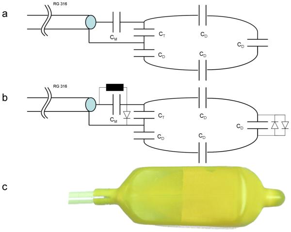
Figure 2.
The ERC circuitry consisted of 6 capacitors for matching, tuning and distributing currents around the coil. The tune and match circuitry exits the rod at the proximal end of balloon at which point the loop coil originates which measures 7 cm long and 3 cm wide. The trERC coil (a) used the following matching, tuning and distributed capacitor values respectively: CM=12 pF, CT=8.2 pF and CD=8.2 pF. The roERC (b) has a similar configuration but with an active diode to create a short across the tune and match circuitry and a passive cross-diode across the distributed capacitor at the tip to detune the loop structure in the presence of induced currents. With the addition of the diodes, the roERC required slightly different capacitor values: CM=10 pF , CT=9.1pF and CD=8.2pF. (c) The completed coil after stretching the original latex cover over the inner balloon and modified electronics.

