Abstract
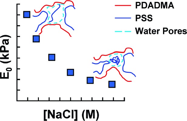
Complexes of sodium poly(4-styrenesulfonate) (NaPSS) and poly(diallyldimethylammonium chloride) (PDADMAC) were formed on mixing equimolar solutions in high salt concentration. Under ultracentrifugal fields, the complex precipitates were transformed into compact polyelectrolyte complexes (CoPECs), which showed extensive porosity. The mechanical properties of CoPECS make them attractive for bioimplants and tissue engineering applications. Free NaPSS chains in the closed pores of CoPECs create excess osmotic pressure, which controls the pore size and contributes to the mechanical resistance of the material. The mechanical properties of CoPECs, modulated by the ionic strength of the doping medium, were studied by uniaxial tensile testing and the stress−strain data were fit to a three-element Maxwell model which revealed at least two regimes of stress relaxation.
Introduction
Intensive research has been recently directed toward designing new materials for biomedical applications. Hydrogels have been of potential use in this respect since they serve as scaffolds with properties similar to the extracellular matrices of many biological tissues.1 A hydrogel has been defined as a three-dimensional water-swollen polymeric network having more than 50 wt % water.2 The amount and distribution of the water phase, especially the formation of pores, strongly influences the mechanical properties of gels. Biot’s poroelastic model3 described the biphasic porous nature of gels. Much of the modeling has focused on articular cartilage, which is a highly hydrated soft tissue between bones and contributes to lubrication and load-bearing.4 The viscoelasticity of articular cartilage results from an interplay between the solid matrix, where the intrinsic viscoelasticity is heavily moderated via chemical and physical cross-links, and the interstitial solution flowing in pores.4,5 Efforts to model the behavior of the material take into account such multiphase components.4,5
Polyelectrolyte complexes (PECs) are amorphous physical hydrogels stabilized by ion pair cross-links (“electrostatic interactions”) between oppositely charged polyelectrolytes.6 PECs have long been recognized for having certain properties similar to those of extracellular matrices in biological tissues.7−9 The formation of a polyelectrolyte complex is governed by many factors, including chemical composition, the concentration of the polyion solutions, rate and order of mixing, ionic strength, pH, temperature, and relative molecular weights of the interacting polyelectrolytes.10 This set of conditions determines the morphology, composition, and mechanical integrity of the complexes formed, from nanoparticles to macroscopic gels.11
As-prepared PECs may be considered hydrogels at the maximum cross-link density, similar to the well-known alginate gels, where alginate molecules are held together by divalent ions, usually calcium.12 The mechanical properties of PECs are controlled by their ion pair cross-linking density, which is, in turn, controlled by the ionic strength of the surrounding medium. The ionic cross-links are thermodynamically reversible,13 their dissociation governed by the following equilibrium:14
| 1 |
where Pol+ and Pol− represent the positive and negative polyelectrolyte repeat units respectively, C+ and A− are counterions (such as Na+ and Cl−), c refers to components in the complex phase. PECs are somewhat unconventional hydrogels: unlike the usual approach to preparing hydrogels, where a base of un-cross-linked hydrophilic polymer is modified with a few percent cross-linker, PECs start in the fully cross-linked state and are transformed to less cross-linked materials with the addition of a salt via eq 1. Quantitative studies of the mechanical properties of PECs, especially in the thin film “multilayer” morphology, have been undertaken using techniques such as nanoindentation,15 osmotic swelling,16 strain-induced elastic buckling instability17 and the quartz crystal microbalance.18 We have used direct micromechanical methods for measuring the tensile and damping properties of polyelectrolyte multilayers.13,19
We recently reported a large scale method for preparing rugged PEC articles via ultracentrifigation20 which were termed compact polyelectrolyte complexes (CoPECs). An unexpected finding was the spontaneous formation of micropores and nonstoichiometric CoPECs from stoichiometric mixtures of polyelectrolytes. We hypothesized that the polyelectrolyte in excess had phase-separated during centrifugal compaction into micropores, and that the efficient damping and mechanical characteristics, similar to the intervertebral disk, were largely due to the closed-shell pores created and maintained by the osmotic pressure of the excess polyelectrolyte. Closed polyelectrolyte-filled pores provide significant restoring force to the composite, just as excess biopolyelectrolyes do in cartilage.21 In the present work, we investigate the morphology of CoPECs, demonstrating closed shell pores, and we examine mechanical response under uniaxial strain. The tensile behavior of the CoPECs was well fitted to a three-element Wiechert model, which is widely used in accounting for the mechanical response of biphasic materials, including cartilage.22
Materials and Methods
Poly(4-styrenesulfonic acid) (PSS Mw = 7.5 × 10⁴ g/mol, Mw/Mn = 1.4) and poly(diallyldimethylammonium chloride) (PDADMAC Mw = 40 × 104 to 50 × 104 g/mol, Mw/Mn = 2.09) were used as received from Aldrich. NaCl (ACS grade) from Aldrich was used to adjust the ionic strength of the polyelectrolyte solutions and for doping solutions. All solutions were prepared using deionized water (Barnstead, E-pure).
For the mechanical tests, the complexes were prepared from equimolar polyelectrolyte solutions (0.5 M by monomer units) in 2.5 M NaCl. The pH of the solutions was adjusted to 7 using 1 M NaOH and 1 M HCl. The 20 mL samples of the cationic and anionic polyelectrolytes were mixed by adding the PSS solution to PDADMAC solution while stirring for 10−15 min to form an amorphous opaque blob of complexed polyelectrolytes with entrapped solution. These precipitates were centrifuged using a Beckman Coulter Optima XL-100 K ultracentrifuge and polycarbonate thick wall centrifuge tubes that fit the type 70 Ti rotor (tube angle 23°). Centrifugation was performed at 190 000 g for 4 h at 25 °C.
To test for free PSS chains in pores of CoPEC, samples were prepared by mixing 10 mL of 0.5 M PDADMAC in 2.5 M NaCl with 10 mL of each of PSS prepared in 2.5 M NaCl at the following monomer concentrations: 0.3, 0.4, 0.5, 0.6, 0.7, 0.8, and 0.9 M, all at pH 7. The precipitates collected after stirring were ultracentrifuged. UV−vis spectra of the supernate, before and after centrifugation, were also collected. Each of the chunks of CoPEC was first washed with water, then immersed in 50 mL water and chopped into small pieces, ca. 1 mm on a side, with a razor blade. The supernate for each sample was collected after 24 h of soaking and the CoPEC pieces were washed, soaked again in 50 mL of fresh water, and chopped into smaller pieces. This procedure was repeated each day over a period of 9 days, and the supernate was collected every 24 h. UV−vis spectra of the supernates were collected using a Cary 100 Bio UV−vis spectrophotometer. The absorbance peaks at 225 nm correspond to the PSS. The amount of PSS released from each soaking and chopping cycle was calculated using a PSS calibration curve.
Sample preparation for elemental analysis involved washing the desired complexes for 2 h in water, and then drying them for 8 h at 80 °C under vacuum.
For microscope imaging, PSS/PDADMA CoPEC samples were immersed in either water or 0.1 M NaCl for 48 h and 10 μm slices were cut using a cryostat microtome (Leica CM 1850) and imaged, at 100× magnification, using a Nikon Eclipse Ti inverted microscope equipped with photometrics CoolSNAP HQ2 camera and NIS-Elements AR 3.0 imaging software.
Uniaxial stress/strain behavior was recorded on a tensile testing machine (Thümler GmbH, Model: TH 2730) equipped with a 5 N load cell. The samples used for all mechanical tests were rectangular (average dimensions: length 15 mm, width 5 mm, and thickness 2 mm) cut from centrifuged PSS/PDADMA CoPEC.
For stress relaxation experiments an instantaneous strain of 2% was set and the decrease in stress was followed versus time. PSS/PDADMA CoPECS were doped in different NaCl concentrations for 3 h (sufficient time for doping to reach equilibrium) before testing. The wet samples were mounted on two plastic grips and stress relaxation monitored for 200 s. For modeling the dynamic behavior of the complex at different strain rates, PSS/PDADMA CoPECs doped in 0.5 M NaCl for 3 h were used. Strains were maintained below 2%.
To study the kinetics of doping of the complex in different [NaCl], the tensile apparatus was fitted with a glass cell which allowed the CoPEC to be bathed in salt solution during testing. Stress−strain curves were collected every 5 min at a strain rate of 1 mm min−1 up to 2% strain. Modulii for these kinetics experiments were determined from the slope of the stress−strain curve between 1 and 1.5% strain. In all experiments the temperature was 23 ± 1 °C.
To determine the strain to break for CoPEC samples they were doped in 0.1, 0.5, and 1.0 M NaCl for 3 h and stretched at 1 mm min−1 until the sample failed. Samples were maintained wetted with their respective doping solutions. Force−elongation plots were converted to true stress/strain curves to account for the change in area with deformation.23
Results and Discussion
PSS/PDADMA Complex Morphology
Polyelectrolyte complexes are historically prepared by mixing solutions of oppositely charged polyelectrolytes.10,24 A more recent method for preparing PECs is via layer by layer alternating deposition, yielding polyelectrolyte multilayers (PEMU) thin films.25−27 A significant difference between solution-precipitated and multilayered PECs is that the latter proceeds with good matching of positive and negative polyelectrolyte charges, yielding stoichiometric complexes with low counterion and minimized water content.28 In solution-precipitation, polyvalent interactions between strands of oppositely charged polyelectrolytes present kinetic limitations to their complete pairing. Precipitated complexes are thus diffuse with little mechanical integrity. If aggressive ternary solvents (water, organic phase, and salt) are employed, the precipitates may be redissolved and then cast as tough films.6
The CoPECs reported here were prepared from equimolar solutions of NaPSS and PDADMAC, mixed under stirring. The white opaque blob of precipitated complex entrained a considerable portion of the solution. Under an ultracentrifugal field, most of the trapped aqueous solution was expressed from the precipitate, leaving behind a compact, transparent robust piece of material. The CoPEC was clearly formed under nonequilibrium conditions, as, even for stoichiometic mixtures, the integrity and toughness of the CoPEC was controlled by all experimental variables, including mixing order.29 After considerable exploration of these variables, it was found that 0.5 M for each polyelectrolyte in 2.5 M NaCl yielded tough, compact material suitable for mechanical testing. This concentration of salt provides for strong doping of the complex (without dissolving it), renders the material quite soft, and permits interchain diffusion on the time scale of the centrifugation.30 The ability to reform PECs into permanent shapes under conditions of salt doping is termed “saloplasticity.”20
The PECs are composed of two phases: a polymer matrix and interstitial solution. The polymer matrix consists of interacting PSS and PDADMA forming the ionic cross-links of the polymer network, termed intrinsic sites. Other polyelectrolyte repeat units are compensated by counterions from the solution, forming doped or extrinsic sites. Elemental analysis of dried PSS/PDADMA CoPEC revealed a 14% excess of PSS repeat units compared to PDADMA, contrary to many reports on PECs,31,32 where nondilute solutions of polyelectrolytes are generally found to precipitate as stoichiometric complexes. On the other hand, the parameter space of PEC formation is vast, permitting specific conditions, such as significant molecular weight difference, extreme dilution, or nonstoichiometric mixing ratios, to yield nonstoichiometric complexes, many of which are soluble.33−35 In the present case, we have observed that the order and rate of mixing and the ionic strength of the mixed solutions affect PEC stoichiometry. In addition to kinetic control, there may also be some thermodynamic preference for PSS in the complex. It was found that at room temperature NaPSS precipitates in 4.9 M NaCl (just beyond the Θ solvent condition)36 while PDADMAC remains soluble even in saturated NaCl (see Supporting Information Figure S1). Thus, it is likely that 2.5 M NaCl is a better solvent for PDADMAC than for NaPSS, which would drive the PSS into the complex phase.
Within the CoPEC, excess PSS can exist in two forms:20 nonstoichiometric extrinsic sites; or free chains trapped in the aqueous pore phase. We have shown that the water content of these CoPECs exceeds by far the intrinsic hydration attributed to ion pair cross-links, and we assumed this extra water resides in pores.20 Porosity in hydrogels37−39 is a desirable feature of bioimplants, providing a path for the transportation of nutrients.39 Porosity in PECs has been described previously. For example, Mendelsohn et al.40 have induced pores in poly(acrylic acid) /poly(allylamine hydrochloride) multilayers by changing the pH, which causes protonation within the multilayer followed by phase separation. Spontaneous pore formation in CoPECs is probably driven by the osmotic pressure of excess free PSS.20 A similar mechanism was described for pore generation during the decomposition of multilayers exposed to high salt concentration.41 A representation of the CoPEC structure is depicted in Scheme 1.
Scheme 1. Representation of the Internal Structure of a PSS/PDADMA CoPEC.
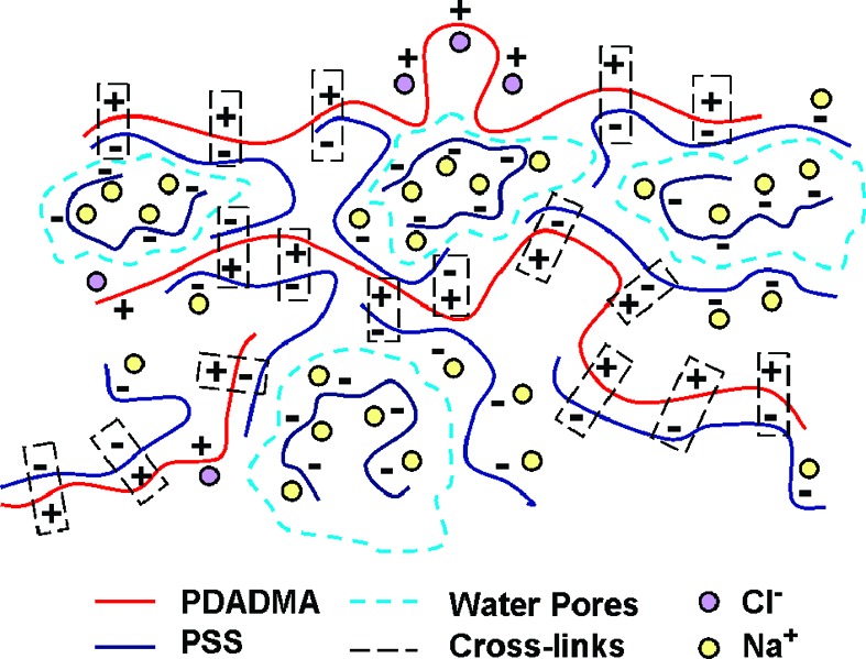
PDADMA chains, PSS chains, and counterions are shown. Intrinsic sites (ion pair crosslinks) are indicated by the rectangles. Non-cross-linked extrinsic sites are compensated by counterions. Pores, boundaries indicated by dotted blue lines, contain excess free PSS chains.
The number of pores remains constant as a function of the concentration of external salt bathing solution, but the pore size (volume) increases with decreasing salt concentration. Figure 1 depicts micrographs of PSS/PDADMA immersed in 0.1 M NaCl and pure water. The osmotic pressure of polyelectrolytes, caused mainly by counterions, is highly dependent on the ionic strength of the medium.42 The activity of excess sodium counterions from PSS trapped in pores causes greater osmotic pressure inside the CoPEC.
Figure 1.
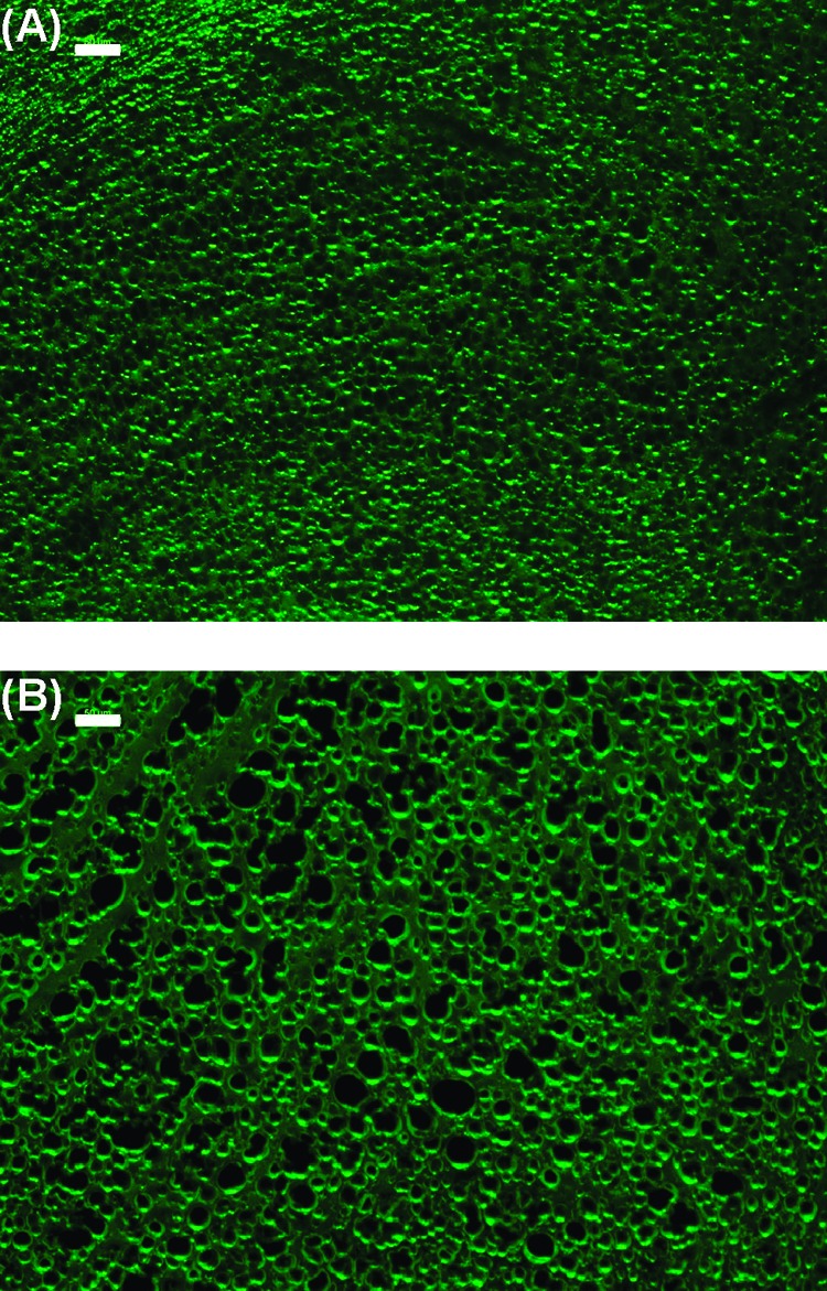
Micrographs of 10 μm thick sections of PSS/PDADMA CoPEC immersed in 0.1 M NaCl (A) and 0.0 M NaCl (B), each for 48 h. The scale bar is 50 μm.
The micrographs strongly suggest a closed-cell structure of the pores, which would be required to trap free PSS. To prove the closed-shell morphology, PSS was released from the pores by chopping the CoPEC into smaller pieces with a razor blade under water. The UV−vis spectrum of the solution revealed the amount of PSS released (band at 225 nm which corresponds to PSS absorption: Supporting Information). This procedure could be repeated each day after soaking the remaining pieces in water because the complex continued to expand slowly.
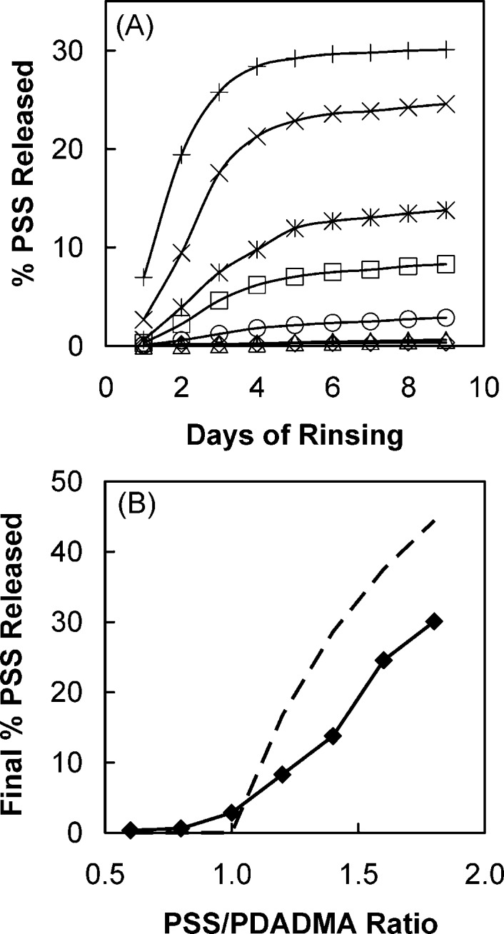
As a qualitative test for PDADMAC release, NaPSS was added to check for complex formation. All the rinse solutions remained clear after the addition of PSS, indicating the absence of PDADMAC. In contrast the presence of PSS was revealed by a precipitate that rapidly formed on the addition of PDADMA. Figure 2 (A) shows the cumulative percentage of PSS released from the pores of PSS/PDADMA complex samples into the rinsing water over the course of several days.
Figure 2.
(A) Cumulative percentage of PSS (relative to initial PSS content in the complex) released vs time from PSS/PDADMA CoPECs rinsed and chopped daily. CoPECs were prepared with 0.5 M PDADMA solution and equal volumes of PSS solutions: 0.3 M (◇), 0.4 M (Δ), 0.5 M (○), 0.6 M (◻), 0.7 M (∗), 0.8 M (×), and 0.9 M (+). (B) Total release of PSS after 9 days of rinsing and chopping (◆). The dotted line represents the excess (i.e., beyond stoichiometric) PSS.
These findings are consistent with the accumulation of free PSS in pores with closed shells (i.e., no interconnectivity). For nonstoichiometric CoPECs (PSS:PDADMA > 1), the higher the ratio of PSS:PDADMA, the more PSS was found trapped in pores. More trapped PSS yielded greater swelling of CoPECs. For CoPECs prepared with excess PDADMAC, the small amount of PSS detected in the rinsing water (Supporting Information, Figure S2) is most probably from microscopic complex particles released during chopping. The unexpected result in our experiments was that stoichiometric (1:1) ratios of PSS:PDADMA did not yield stoichiometric complexes.
In Figure 2B, the percentage of the total PSS content released, after 9 days, from the samples prepared under various stoichiometries is plotted and compared to the theoretical value for release of all excess PSS. For the 1:1 PSS/PDADMA 2.8% PSS was released. This result was confirmed by elemental analysis, which showed that the excess PSS in the CoPEC decreased from 14% to 11.2% after the 9-day chopping and rinsing procedure.
All excess PSS is not released for two reasons: not all pores are opened during sequential choppings; and some PSS may exist as nonstoichiometeric or trapped extrinsic sites. As expected for closed-shell pores, a control sample of 1:1 CoPEC released negligible amounts of PSS over 9 days soaking in water (Supporting Information).
For 1:1 mixing of polyelectrolytes during CoPEC formation, one would expect excess PDADMA to remain in the supernate if centrifuged CoPECs contain excess PSS. Accordingly, the supernate yielded precipitates on addition of PSS, but showed no reaction to the addition of PDADMA, indicating the presence of extra PDADMA in the supernate. However, the UV−vis spectrum of the visibly clear supernate showed a strong band at 225 nm (Supporting Information, Figure S4), attributed to a minor amount of PSS entrained as quasisoluble complexes that showed a hydrodynamic radius of 37 nm by dynamic light scattering (Supporting Information).
Viscoelasticity of PSS/PDADMA CoPECs
Most polymeric materials, including polymer gels, exhibit viscoelastic behavior on mechanical deformation.43 Our prior work on mechanical properties with microporous saloplastic CoPECs was performed in a shear rheometer with plate−plate configuration.20 In one perceived application for CoPECs, as replacements for intervertebral discs,20 deformation is in a uniaxial direction. Uniaxial tensile tests44 are especially useful for long-term deformations.45 For small deformations, with Poisson ratios close to 0.5, the elastic modulus E(t) is three times the shear modulus G(t).43 In addition, the classical uniaxial strain configuration allowed us to bathe samples in different salt concentrations to observe relatively rapid equilibration in response to different doping levels.13
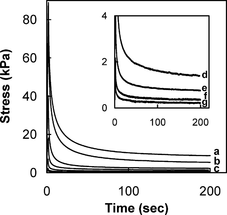
Stress relaxation43 (with characteristic relaxation times τ) was performed with CoPECs at r.t using various concentrations of NaCl to dope the material. Figure 3 depicts the stress relaxation behavior of 1:1 PSS/PDADMA CoPEC equilibrated in NaCl solutions of ionic strengths varying from 0.1 to 1.5 M. The samples were rapidly (10 mm min−1) uniaxially strained by 2% then allowed to relax. A pseudo steady state was attained at an equilibrium stress, σeq, for t > 150 s. In contrast, nonporous thin (micrometer) PSS/PDADMA multilayers attained pseudo steady state much more quickly (70 ms).13 Relaxation mechanisms in saturated porous media are well interpreted by the linear biphasic poroviscoelastic model (BPVE) used to account for the viscoelasticity of articular cartilage.4,5,46 In this model, two mechanisms are involved in the apparent viscoelasticity of the cartilage: a water flow-dependent mechanism from the frictional drag of fluid flowing in pores, and a water flow-independent mechanism, which involves energy-dissipating interactions within the solid matrix itself. Modeling stress relaxation behavior of the articular cartilage leads to the conclusion that short-term relaxation response is mainly governed by the fluid flow-independent mechanism and long-term relaxation is governed by the fluid flow-dependent mechanism. This explains the difference between the relaxation behavior of a (nonporous) PEMU and a (porous) CoPEC.
Figure 3.
Stress relaxation of (1:1) PSS/PDADMA CoPECs doped with different NaCl concentrations: 0.1 M (a), 0.25 M (b), 0.5 M (c), 0.75 M (d), 1 M (e), 1.25 M (f), and 1.5 M (g). The inset shows curves e−g. Samples remained wetted by the doping solution.
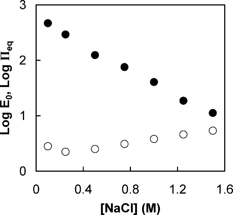
A relaxed viscoelastic solid at equilibrium is equivalent to a perfect elastic solid.43 The equilibrium elastic modulus values of 1:1 PSS/PDADMA doped in solutions of different NaCl concentrations, determined at pseudo steady state, are almost 2 orders of magnitude less than those of PSS/PDADMA multilayers in the range of salt concentration studied13 (Figure 4). For a given material, the elastic modulus is known to decrease with increasing degree of swelling.47
Figure 4.
Dependence of the equilibrium elastic modulus and equilibrium osmotic pressure in 1:1 PSS/PDADMA CoPEC on the doping NaCl concentration. Key: (●) measured elastic modulus; (○) equilibrium osmotic pressure contributed by PSS in pores. Modulus and osmotic pressure are in kPa.
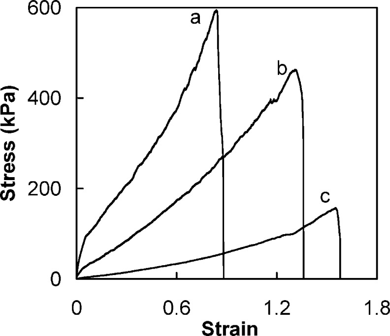
In CoPECs, as in PEMUs, a strong decrease in elastic modulus is expected as salt doping breaks ion pairing cross-links, as illustrated by eq 1.13 There are two major differences between the two PEC morphologies: first, the bulk modulus of CoPECs is considerably lower than that of PEMUs. This is due to the highly porous morphology of the former, where the modulus of the PEC “struts” is convoluted with that of the aqueous pores. A second major difference is in the extent to which CoPECs can be deformed. As shown in Figure 5, the stress/strain behavior was roughly linear over a range of 80% to 150% uniaxial strain, depending on doping level. The strain to break also depended on doping. In comparison, the same complex as a PEMU was not linearly or reversibly deformed past a few percent strain.13
Figure 5.
True stress−true strain plots for PSS/PDADMA CoPECs doped in 0.1 M (a), 0.5 M (b), and 1 M (c) NaCl solutions and stretched to breaking at 1 mm min−1.
Polyelectrolyte Complexes: Cartilage Mimics
Materials with elastic modulus in the kPa range are of interest for use as biomaterials, since most soft biological tissues are within this range of stiffness. For example, the elastic modulus of articular cartilage, determined from equilibrium stress−strain data under compression, was found to vary between 300 and 800 kPa.48 Some CoPECs, when fully hydrated, have been shown to possess mechanical properties similarities to articular cartilage.20 Articular cartilage has pores in which negatively charged macromolecules, proteoglycans, are dispersed, affecting osmotic swelling and mechanical resistance of the tissue under load.49 The contribution of the osmotic component in cartilage was found to be almost one-third of the total stiffness.50
Collagen fibrils introduce anisotropic mechanical properties in cartilage: it is known that the tensile modulus is greater than the compressive modulus. This anisotropy is also manifested in a Poisson’s ratio approaching 0.1.51 However, the CoPEC investigated here was isotropic, with a measured Poisson’s ratio of 0.47. Korhonen and Jurvelin have shown that the compression and tension modulii in an isotropic poroelastic material are symmetrical and that they are modulated the same by osmotic pressure.52 We have estimated the contribution of the osmotic stress of the PSS in the pores to the total stiffness of the complex at equilibrium. An estimate of PSS concentration in the pores at equilibrium swelling is presented in the Supporting Information. Literature values53 for the osmotic pressure of PSS in NaCl were extrapolated to polyelectrolyte and salt concentrations employed in the present study, and are plotted in Figure 4. At lower salt concentrations, the equilibrium osmotic pressure in the pores is only a small fraction of the total modulus, but it becomes a significant fraction at the higher salt concentrations. Interestingly, the osmotic pressure appears to converge with the bulk modulus in salt concentrations at which the complex is no longer stable and dissociates. The concentration for this osmotic instability is highly dependent on salt and polyelectrolyte type. For example, PAA/PDADMA complexes are stable up to 0.6 M NaCl54 and PSS/PDADMA PECs are stable up to 0.75 M NaClO4.55 It is also possible to cause an osmotic “explosion” by shifting the internal charge of a PEC e.g. by changing pH.56−58
Adapting the biphasic linear viscoelastic model for analyzing cartilage,22 we applied a generalized Maxwell model (or Wiechert model),45 to understand the stress−strain behavior of PSS/PDADMA CoPECs. Scheme 2 represents such a model, restricted to two Maxwell elements (series spring and dashpot) and one isolated spring.
Scheme 2. Wiechert Model, or Generalized Maxwell Model, with an Isolated Spring and two Maxwell Elements.
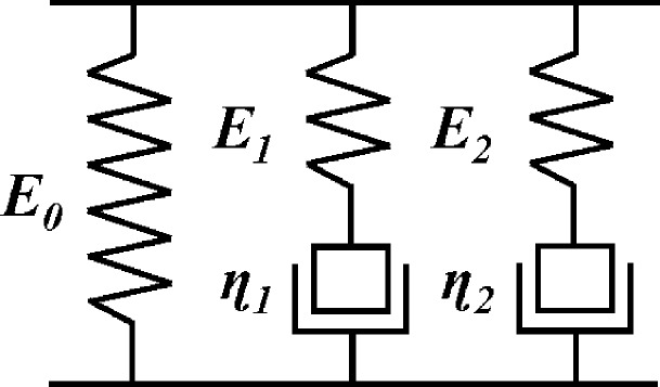
E0, E1, and E2 represent the elastic modulus of the isolated spring, spring of the first Maxwell element, and spring of the second Maxwell, respectively. η1 and η2 are the viscosities of the dashpots in the first and second Maxwell elements, respectively.
An object is to represent the system with the fewest number of elements. The two Maxwell elements in the model represent short-term and long-term relaxing mechanisms mentioned earlier. The total stress (σ) experienced under a constant strain is the sum of the stresses in each element.43
| 2 |
σe, σv1, and σv2 are the stress of the isolated spring, the first Maxwell element, and the second Maxwell element, respectively. The stress−strain relation of such a model is:44
 |
3 |
where ε is the strain, dε/dt is the strain rate, and E0, E1, and E2 are the elastic moduli of the isolated spring, spring of the first Maxwell element, and spring of the second Maxwell element, respectively. τ1 and τ2 are the relaxation times of the dashpots in the first and second Maxwell elements respectively, related to the viscosity of the dashpot by:
| 4 |
The stress−strain behavior of 1:1 PSS/PDADMA CoPEC doped in 0.5 M NaCl is shown in Figure 6. The sample was strained to 2% at rates from 2 to 20 mm min−1 (14 to 140% min−1).
Figure 6.
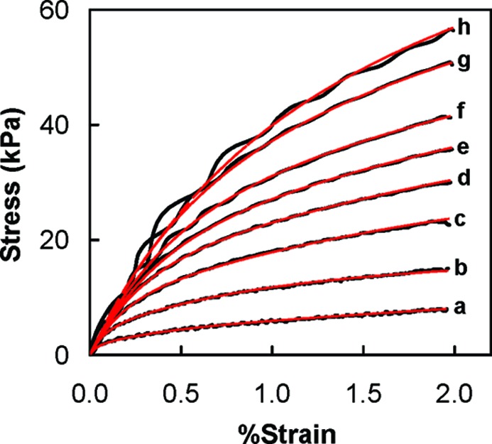
Stress−strain curves of a PSS/PDADMA CoPEC doped in 0.5 M NaCl at different strain rates: (a) 2, (b) 5, (c) 7.5, (d) 10, (e) 12, (f) 15, and (g) 20 mm/min. The red curves are fits to eq 3.
The results for different strain rates were fit to eq 3. The fits are shown in Figure 6 and the fitting parameters are listed in Table 1. The value for E0 was taken from Figure 4. The model fits well for stress−strain curves at different strain rates. Fit parameters were almost identical for each strain rate.
Table 1. Parameters of the fitting equation (eq 3) at different strain rates.
| strain rate (mm/min) | E0 (kPa) | E1 (kPa) | τ1 (s) | E2 (kPa) | τ2 (s) |
|---|---|---|---|---|---|
| 2 | 124 | 4800 | 0.31 | 1305 | 2.95 |
| 5 | 124 | 4710 | 0.30 | 1065 | 3.00 |
| 7.5 | 124 | 4820 | 0.31 | 1087 | 2.85 |
| 10 | 124 | 4830 | 0.31 | 1090 | 2.83 |
| 12 | 124 | 4820 | 0.33 | 1170 | 2.65 |
| 15 | 124 | 5300 | 0.32 | 1200 | 2.80 |
| 20 | 124 | 4980 | 0.32 | 1180 | 2.71 |
| av. | 124 | 4894 | 0.31 | 1157 | 2.83 |
These findings may be combined with previous observations on micrometer thick PSS/PDADMA multilayers, which showed strain relaxation with a time constant on the order of 10 ms and E0 in the MPa range.13 For example, under the same conditions (0.5 M NaCl, room temperature) as the CoPEC analyzed in Figure 6, the PEMU had a E0 of 5 MPa.13 The key difference between the morphologies was the pore content of the CoPEC. PEMUs are generally nonporous (or the “porosity” is on the order of molecular dimensions59), although pore formation has been observed in decomposing PEMUs.41
The three time regimes for relaxation in CoPECs are rationalized as follows: the fastest τ, ca. 10 ms previously observed in micro samples,13 is attributed to molecular scale relaxations of the kind observed by NMR measurements on PEMUs.60 This τ is too short to observe in the current experiment. The τ1 of about 0.3 s is assigned to mechanical relaxation of the solid PEC framework. τ2, at about 3 s, is due to the hydrostatic relaxation of water in the pores, which, though closed-shell, allow flow of water by transport though the micrometer thick walls of solid polyelectrolyte complex. The mechanical properties of cartilage are often rationalized using such a combination of the response of the framework and a hydrostatic (water) component.4,5,46
Doping Kinetics and Diffusion of Extrinsic Sites
Stress−strain measurements were usually performed after samples had thoroughly equilibrated with the salt solutions in which they were immersed. Sufficient time allowed the CoPECs to become homogeneously doped to equilibrium doping levels (eq 1). The doping level in a specific salt solution can be determined using the doping constant (Kdop).61
| 5 |
where aA− and aC+ are the activities of the corresponding ions; y and (1 − y) are the fractions of the extrinsic (doping) and intrinsic sites, respectively. When the salt concentration changes, ions move into, or out of, the complex. Figure 7 illustrates how the modulus of a sample of PSS/PDADMA CoPEC changes with time when it goes from a solution of higher (2.5M) to lower salt concentration. The material becomes stiffer, reaching equilibrium after some time. In 2.5 M NaCl degree of cross-linking is about 35%.13
Figure 7.
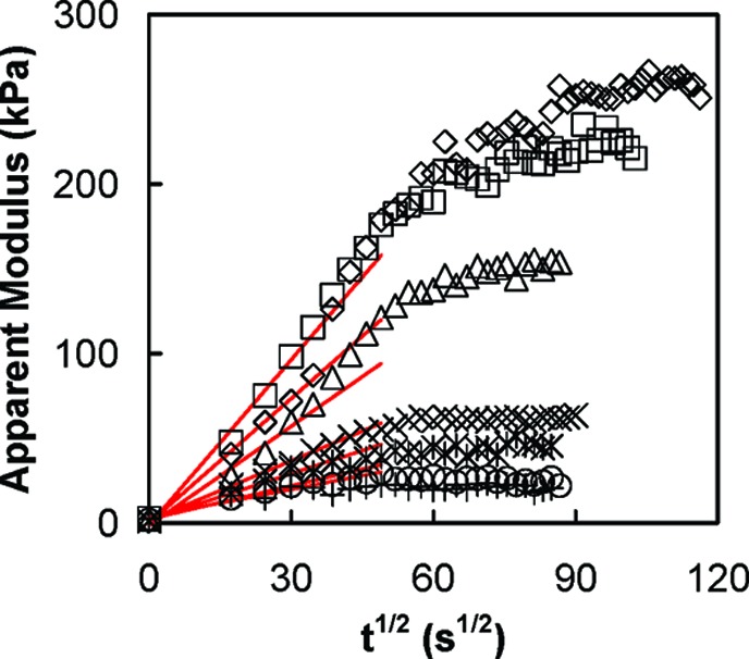
Modulus versus square root of time for 1:1 PSS/PDADMA CoPEC doped in NaCl of concentration: 0.1 M (◇); 0.25 M (◻); 0.5 M (Δ); 0.75 M (×); 1 M (∗); 1.25 M (○); 1.5 M (+). E was measured between 1% and 1.5% strain at a strain rate of 1 mm min−1. The solid lines are linear fits for the modulus at short times.
Since each extrinsic site is charge-balanced by a counterion, their diffusion into (or out of) the complex under a concentration gradient is coupled. The coupled interdiffusion coefficient, DAB, between two species A and B, well-known in classical ion exchange resins, is given by62
| 6 |
where DA and DB are their individual (uncoupled) diffusion coefficients, zA and zB their charges, and CA and CB their concentrations, respectively. All quantities are those within the exchanger. Equation 6 reveals an interesting difference between PECs, which are “reluctant” exchangers where the number of ion exchange sites is created by external salt doping,61 and classical fixed site exchangers, such as ion exchange resins.62 In the latter, the interdiffusion coefficient depends on the relative ion concentrations (CA vs CB), which varies during the course of an exchange, whereas in the present case CA = CB = C and
| 7 |
Although eq 7 suggests DAB is independent of C, the individual diffusion coefficients DA and DB themselves depend strongly on C.61 If DB is the diffusion coefficient for a Pol− extrinsic site and DA for a Na+ counterion, and DA ≫ DB (a reasonable assumption)
| 8 |
In this case, the well-known ion exchanger rule62 that “the ion present in smaller concentration has the stronger effect on the rate of interdiffusion” reduces to “the interdiffusion coefficient is twice the coefficient of the slower species.”
Apparent diffusion coefficients were extracted from the modulus data (Figure 7) assuming the measured modulus is the average of contributions from doped and undoped CoPEC (see Supporting Information for details), and the well-known relationship for diffusion layer thickness Δ, Δ=(2Dappt)1/2
The measured modulus vs time is given by
 |
9 |
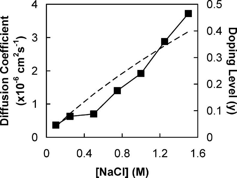
where w and h are the width and the thickness of a sample respectively, Edoped is the modulus of the starting complex (in 2.5 M NaCl), and Eundoped is the equilibrium modulus in the less doped state in a given salt solution. Figure 8 also includes an estimate of the doping level, y, using a doping constant63Kdop = 0.27. Figure 8 shows that Dapp increases with doping, which is expected.30
Figure 8.
Diffusion coefficient Dapp of sites and doping level in PSS/PDADMA CoPEC as a function of [NaCl]. (◼) Diffusion coefficients. The dashed line is the doping level calculated from eq 5.
Unfortunately, diffusion coefficients estimated from Figure 8 are not the same as the bulk diffusion coefficient, DAB. The CoPEC is a composite of solid and liquid phases, in which ion transport in the latter can “short circuit” transport in the former. That is, instead of diffusing through solid PEC, an ion is able to diffuse through the liquid phase. Thus, the apparent diffusion coefficients in Figure 8 are much closer to aqueous values, and many orders of magnitude larger than bulk diffusion. For example, diffusion of PSS in a (continuous) PEMU phase was found to be about 6 × 10⁻¹⁷ cm2 s−1 in 0.8 M NaCl,30 whereas the apparent diffusion coefficient for the porous system is about 10−6 cm2 s−1 (Figure 8). While the biphasic nature of CoPECs complicates the diffusion model, it is, in fact, an enormous advantage in accelerating the response time to doping for CoPECs. If ions had to be transported through bulk PEC without traveling via aqueous pore phase a PEC of millimeter dimensions could not be quickly doped to equilibrium.
Conclusion
While CoPECs and PEMUs are made from the same materials, it is clear that porosity provides a significant dimension for controlling the mechanical properties of polyelectrolyte complexes. Specifically, when compacted as described here, a complex is much softer than the film obtained by the layer-by-layer adsorption method. At the same time, porosity endows the complex with significantly expanded linear elastic response, even though the bulk polymer retains an extremely high cross-link density. The importance of osmotic pressure generated by trapped macromolecules has been highlighted. Nonstoichiometry probably has an important role in the spontaneous generation of pores. The mechanical response of CoPECs falls into the range of articular cartilage. A systematic study of preparation conditions vs porosity and properties of the CoPEC is underway.
Acknowledgments
The authors are grateful to Dr. X. Jia for help with complex slicing, to M. D. Moussallem for the help with tensile setup, to A. M. Lehaf for help with micrographs, to Z. G. Estephan for help with dynamic light scattering experiments, and to M. Z. Markarian for discussion on data fitting. This work was supported by the National Institutes of Health (Grant R01EB006158) and the National Science Foundation Center (Grant DMR-0939850).
Supporting Information Available
Text discussing turbidimetry experiments, UV−vis absorption of spectra, percentage of PSS released, correlation function of the supernate after centrifugation, calculation of the concentration of extra PSS in the pores of complexes doped at different ionic strength, determination of the osmotic pressure exerted by PSS, and derivation of the reactive diffusion equation, with figures showing scattering of NaPSS and PDADMAC solutions. This material is available free of charge via the Internet at http://pubs.acs.org.
Funding Statement
National Institutes of Health, United States
Supplementary Material
References
- Peng H. T.; Martineau L.; Shek P. N. J. Mater. Sci. Mater. Med. 2007, 18, 975–986. [DOI] [PubMed] [Google Scholar]
- Tanaka Y.; Gong J. P.; Osada Y. Prog. Polym. Sci. 2005, 30, 1–9. [Google Scholar]
- Biot M. A. J. Appl. Phys. 1955, 26, 182–185. [Google Scholar]
- Mak A. F. J. Biomech. Eng. 1986, 108, 123–130. [DOI] [PubMed] [Google Scholar]
- Mow V. C.; Kuei S. C.; Lai W. M.; Armstrong C. G. J. Biomech. Eng. 1980, 102, 73–84. [DOI] [PubMed] [Google Scholar]
- Michaels A. S.; Bixler H. J. Kirk-Othmer Encycl. Chem. Technol. 1968, 16, 117–133. [Google Scholar]
- Hejčl A.; Lesný P.; Přádný M.; Šedý J.; Zámečník J.; Jendelová P.; Michálek J.; Syková E. J. Mater. Sci. Mater. Med. 2009, 20, 1571–1577. [DOI] [PubMed] [Google Scholar]
- Luo K.; Yin J. B.; Song Z. J.; Cui L.; Cao B.; Chen X. S. Biomacromolecules 2008, 9, 2653–2661. [DOI] [PubMed] [Google Scholar]
- Chen H. Q.; Fan M. W. J. Bioact. Compat. Polym. 2007, 22, 475–491. [Google Scholar]
- Michaels A. S.; Mir L.; Schneider N. S. J. Phys. Chem. 1965, 69, 1447–1455. [Google Scholar]
- Kříž J.; Dautzenberg H.; Dybal J.; Kurková D. Langmuir 2002, 18, 9594–9599. [Google Scholar]
- Webber R. E.; Shull K. R. Macromolecules 2004, 37, 6153–6160. [Google Scholar]
- Jaber J. A.; Schlenoff J. B. J. Am. Chem. Soc. 2006, 128, 2940–2947. [DOI] [PubMed] [Google Scholar]
- Dubas S. T.; Schlenoff J. B. Langmuir 2001, 17, 7725–7727. [Google Scholar]
- Picart C.; Senger B.; Sengupta K.; Dubreuil F.; Fery A. Colloids Surf. A 2007, 303, 30–36. [Google Scholar]
- Vinogradova O. I.; Andrienko D.; Lulevich V. V.; Nordschild S.; Sukhorukov G. B. Macromolecules 2004, 37, 1113–1117. [Google Scholar]
- Nolte A. J.; Cohen R. E.; Rubner M. F. Macromolecules 2006, 39, 4841–4847. [Google Scholar]
- Guzmán E.; Ritacco H.; Ortega F.; Svitova T.; Radke C. J.; Rubio R. G. J. Phys. Chem. B 2009, 113, 7128–7137. [DOI] [PubMed] [Google Scholar]
- Jaber J. A.; Schlenoff J. B. Chem. Mater. 2006, 18, 5768–5773. [Google Scholar]
- Porcel C. H.; Schlenoff J. B. Biomacromolecules 2009, 10, 2968–2975. [DOI] [PMC free article] [PubMed] [Google Scholar]
- Roughley P. J. Eur. Cells Mater. 2006, 12, 92–101. [DOI] [PubMed] [Google Scholar]
- Ehlers W.; Markert B. J. Biomech. Eng. 2001, 123, 418–424. [DOI] [PubMed] [Google Scholar]
- Roylance D.Stress-Strain Curves; MIT Press: Cambridge, MA, 2001. [Google Scholar]
- Sui Z.; Jaber J. A.; Schlenoff J. B. Macromolecules 2006, 39, 8145–8152. [Google Scholar]
- Iler R. K. J. Colloid Interface Sci. 1966, 21, 569–594. [Google Scholar]
- Decher G. Science 1997, 277, 1232–1237. [Google Scholar]
- Multilayer Thin Films: Sequential Assembly of Nanocomposite Materials; Decher G., Schlenoff J. B., Eds.; Wiley-VCH: Weinheim, Germany, 2003. [Google Scholar]
- Schlenoff J. B.; Ly H.; Li M. J. Am. Chem. Soc. 1998, 120, 7626–7634. [Google Scholar]
- Chen J.; Heitmann J. A.; Hubbe M. A. Colloids Surf., A 2003, 223, 215–230. [Google Scholar]
- Jomaa H. W.; Schlenoff J. B. Macromolecules 2005, 38, 8473–8480. [Google Scholar]
- Dautzenberg H.; Jaeger W.; Kötz J.; Philipp B.; Seidel C.; Stscherbina D.. Polyelectrolytes: Formation, Characterization and Application; Hanser: Munich, Germany, 1994. [Google Scholar]
- Michaels A. S. J. Ind. Eng. Chem. 1965, 57, 32–40. [Google Scholar]
- Kabanov V. A.; Zezin A. B. Pure Appl. Chem. 1984, 56, 343–354. [Google Scholar]
- Karibyants N.; Dautzenberg H. Langmuir 1998, 14, 4427–4434. [Google Scholar]
- Dautzenberg H. Macromolecules 1997, 30, 7810–7815. [Google Scholar]
- Hirose E.; Iwamoto Y.; Norisuye T. Macromolecules 1999, 32, 8629–8634. [Google Scholar]
- Partap S.; Muthutantri A.; Rehman I. U.; Davis G. R.; Darr J. A. J. Mater. Sci. 2007, 42, 3502–3507. [Google Scholar]
- Partap S.; Rehman I.; Jones J. R.; Darr J. A. Adv. Mater. 2006, 18, 501–504. [Google Scholar]
- Spiller K. L.; Laurencin S. J.; Charlton D.; Maher S. A.; Lowman A. M. Acta Biomater. 2008, 4, 17–25. [DOI] [PubMed] [Google Scholar]
- Mendelsohn J. D.; Barrett C. J.; Chan V. V.; Pal A. J.; Mayes A. M.; Rubner M. F. Langmuir 2000, 16, 5017–5023. [Google Scholar]
- Mjahed H.; Voegel J.-C.; Senger B.; Chassepot A.; Rameau A.; Ball V.; Schaaf P.; Boulmedais F. Soft Matter 2009, 5, 2269–2276. [Google Scholar]
- Dobrynin A. V.; Rubinstein M. Prog. Polym. Sci. 2005, 30, 1049–1118. [Google Scholar]
- Ferry J. D.Viscoelastic Properties of Polymers; Wiley-VCH: New York, 1980. [Google Scholar]
- Plaseied A.; Fatemi A. J. Mater. Sci. 2008, 43, 1191–1199. [Google Scholar]
- Roylance D.Engineering Viscoelasticity; MIT Press: Cambridge, MA, 2001. [Google Scholar]
- DiSilvestro M. R.; Zhu Q.; Suh J. K. J. Biomech. Eng. 2001, 123, 198–200. [DOI] [PubMed] [Google Scholar]
- Anseth K. S.; Bowman C. N.; Brannon-Peppas L. Biomaterials 1996, 17, 1647–1657. [DOI] [PubMed] [Google Scholar]
- Korhonen R. K.; Laasanen M. S.; Töyräs J.; Rieppo J.; Hirvonen J.; Helminen H. J.; Jurvelin J. S. J. Biomech. 2002, 35, 903–909. [DOI] [PubMed] [Google Scholar]
- Heneghan P.; Riches P. E. J. Biomech. 2008, 41, 2411–2416. [DOI] [PubMed] [Google Scholar]
- Chahine N. O.; Chen F. H.; Hung C. T.; Ateshian G. A. Biophys. J. 2005, 89, 1543–1550. [DOI] [PMC free article] [PubMed] [Google Scholar]
- Jurvelin J. S.; Buschmann M. D.; Hunziker E. B. J. Biomech. 1997, 30, 235–241. [DOI] [PubMed] [Google Scholar]
- Korhonen R. K.; Jurvelin J. S. Med. Eng. Phys. 2010, 32, 155–160. [DOI] [PubMed] [Google Scholar]
- Koene R. S.; Nicolai T.; Mandel M. Macromolecules 1983, 16, 231–236. [Google Scholar]
- Dubas S. T.; Schlenoff J. B. Macromolecules 2001, 34, 3736–3740. [Google Scholar]
- Jaber J. A.; Schlenoff J. B. Langmuir 2007, 23, 896–901. [DOI] [PubMed] [Google Scholar]
- Sukhishvili S. A.; Granick S. J. Am. Chem. Soc. 2000, 122, 9550–9551. [Google Scholar]
- Kharlampieva E.; Sukhishvili S. A. Langmuir 2003, 19, 1235–1243. [Google Scholar]
- Sui Z.; Schlenoff J. B. Langmuir 2004, 20, 6026–6031. [DOI] [PubMed] [Google Scholar]
- Vaca Chávez F.; Schönhoff M. J. Chem. Phys. 2007, 126, 104705/104701–104705/104707. [DOI] [PubMed] [Google Scholar]
- Smith R. N.; Reven L.; Barrett C. J. Macromolecules 2003, 36, 1876–1881. [Google Scholar]
- Farhat T. R.; Schlenoff J. B. J. Am. Chem. Soc. 2003, 125, 4627–4636. [DOI] [PubMed] [Google Scholar]
- Helfferich F. G.Ion Exchange; McGraw-Hill: New York, 1962. [Google Scholar]
- Schlenoff J. B.; Rmaile A. H.; Bucur C. B. J. Am. Chem. Soc. 2008, 130, 13589–13597. [DOI] [PubMed] [Google Scholar]
Associated Data
This section collects any data citations, data availability statements, or supplementary materials included in this article.


