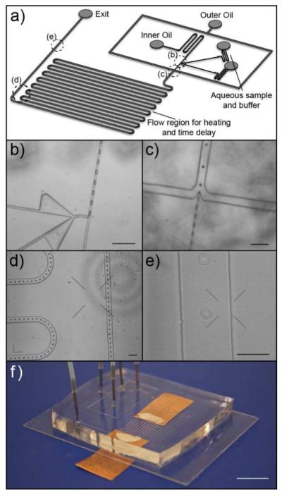
Figure 1.

Microfluidic system for droplet formation and manipulation. (a) Schematic showing the overall chip design. The dotted circles labeled (b-e) in the schematic represent regions of the chip that are shown in the corresponding panels (b-e). In this chip design, the droplets were first formed using a T-channel geometry (b), after which the spacing between the droplets was adjusted using hydrodynamic focusing (c). The droplet stream then flow through a serpentine channel system (d) – which may be useful for different droplet manipulations such as for continuous-flow PCR or simply as a delay line to allow time for hybridization of DNA or binding of protein targets - before each droplet was interrogated at the detection region (e). (f) Photograph of a fully assembled chip with tubing and interconnects; the electrical connections (copper pads) attached to the underside of the cover glass, which was patterned with ITO electrodes, allow for on-chip heating. Scale bars in (b-d) represent 200 μm; scale bars in (e) and (f) represent 100 μm and 10 mm respectively.
