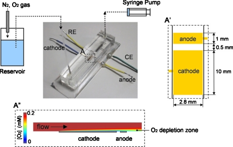
Figure 6.
Schematic illustration of a microfluidic biofuel cell consisting of an upstream biocathode and a downstream bioanode integrated in a PDMS structure with immobilized enzymes as catalysts. A cross-sectional view of the O2 distribution along the channel is shown at the bottom. Reproduced with permission from Togo et al., Environ. Sci. Technol.ESTHAG0013-936X 178, 53 (2008). Copyright © 2008 by Elsevier.

