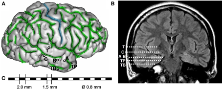
Figure 2.
Example of SEEG exploration in patient with mesial temporal lobe epilepsy. (A) Intracerebral implantation scheme. Electrodes are identified by one or two capital letters: A, B and C (medial contacts: amygdala, anterior part of hippocampus, posterior part of hippocampus; lateral contacts: middle temporal gyrus from anterior to posterior part), T (medial contacts, insula; lateral contacts, superior temporal gyrus), TB (medial contacts, entorhinal cortex; lateral contacts, temporo-basal cortex), TP (temporal pole). (B) Electrode trajectories reported on MRI data (coronal view). (C) Each intracerebral electrode is composed of 10–15 cylindrical contacts (length: 2 mm, diameter: 0.8 mm, 1.5 mm apart).

