
Figure 2.
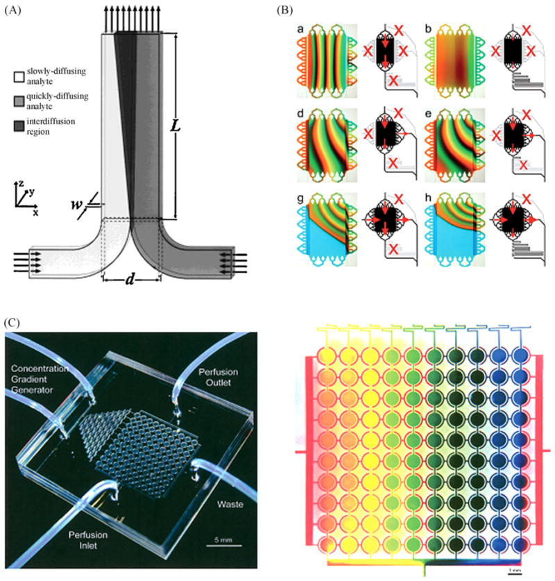
Microfluidic gradient generator. (A) Schematic representation of a T-sensor with two inputs. One can see the diffusion between the two laminar streams along the device [24]. (B) μGG composed of an array of 16 multiplexed inlets which allow 64 combinations of gradient generation. This figure shows gradient shape modification in the central chamber depending of valve state [28]. (C) A microfluidic cell culture array containing 100 cell culture chambers with integrated gradient generators [162]. (D) Zoom on the cell culture array with gradient generation demonstrated using red, blue and yellow dye [162].