
Figure 9.
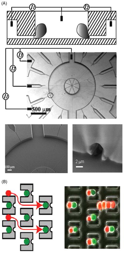
Patch clamp and cell fusion. (A) PDMS micro patch clamp. Top: schematic of the patch clamp device. Middle: picture of the patch clamp array. The small circle indicates one of the patch sites. Bottom: zoom on the patch site [149]. (B) Cell pairing and fusion device: schematic and picture show two different cell types pairing before fusion [148].