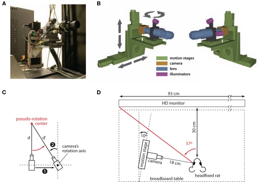
Figure 1.
Schematic diagram of the eye-tracking system. (A) A photograph of the eye tracking system, showing the camera assembly (camera, lens, and infrared LED illuminators) mounted on the motorized stages used to move the camera around the eye of the subject during the calibration procedure (see Materials and Methods). (B) Two 3-dimensional renderings of the eye-tracking system (viewed from two different angles). The colors emphasize the four main components of the system: motorized stages (green), camera (yellow), lens (blue), and illuminators (magenta). The arrows show the motion direction of the linear and rotary motorized stages. (C) The diagram (showing a top view of the camera assembly) illustrates how a horizontal translation of the camera to the right (1) can be combined with a left rotation of the camera about its rotation axis (2) to achieve a pseudo-rotation (red arrow) about a point (red circle) at an arbitrary distance d from the camera itself. This drawing also illustrates how, following the pseudo-rotation, the distance between the camera and the center of the pseudo-rotation changes from d to d′. (D) Diagram showing the position of the camera assembly relative to the imaged eye of the head-fixed rat. The distance of the animal from the screen used for stimulus presentation and the amplitude of the rat's left visual hemifield are also shown.

