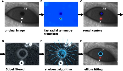
Figure 2.
Illustration of the algorithm to track the eye's pupil and corneal reflection spot. (A) The image of a rat eye under infrared illumination. The dark circular spot is the pupil, while the bright round spot is the reflection of the infrared light source on the surface of the cornea (i.e., the corneal reflection, CR). Other, non-circular reflection spots are visible at the edges of the eyelids. (B) The color map shows the image areas in which the presence of circular features is more likely according to a fast radial symmetry transform. The rough location of both the pupil and CR is correctly extracted. (C) Following the application of the fast radial symmetry transform (see B), the rough centers of the pupil (blue cross) and CR (red spot) are found. (D) A Sobel (edge finding) transform is applied to the image of the eye to find the boundaries of the pupil (gray ring) and CR (white ring). Note that the eye is shown at higher magnification in this panel (as compared to A–C). (E) The previously found rough center of the pupil (see C) is used as a seed point to project a set of “rays” (blue lines) toward the boundary of the pupil itself. The Sobel-filtered image is sampled along each ray and when it crosses a given threshold (proportional to its standard deviation along the ray), an intersection between the ray and the pupil boundary is found (intersections are shown as blue, filled circles). The same procedure is used to find a set of edge points along the CR boundary. (F) An ellipse is fitted to the boundary points of the pupil (blue circle) and CR (red circle) to obtain a precise estimate of their centers.

