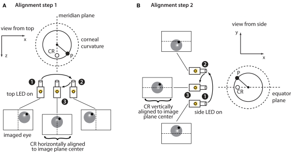
Figure 4.
Horizontal and vertical alignment of the eye with the center of the camera's sensor. (A) When the horizontally aligned (top) infrared LED is turned on a corneal reflection (CR) spot (empty circle) appears halfway along the radius of the corneal curvature (dashed line) that is parallel to the optic axis of the camera. The filled circle shows the pupil position. The large dashed circle shows the corneal curvature/surface. Assuming that the camera's sensor is initially not aligned with the center of the eye (e.g., in position 1), the location of CR can be used as a landmark of the eye's meridian plane to achieve such an alignment by moving the camera's assembly horizontally. The camera is first translated a few mm (from position 1 to position 2) to determine the mm/pixels conversion factor and then makes an additional translation (from position 2 to position 3) that aligns the CR with the center of the horizontal axis of the camera's sensor. Note that because the cornea behaves as a spherical mirror the CR marks the position of the eye's meridian plane throughout all horizontal displacements of the camera's assembly (i.e., the position of the empty circle is the same when the camera is in position 1, 2, and 3). (B) A similar procedure to the one described in (A) is used to vertically align the camera's sensor to the eye's equator plane. In this case, the vertically aligned (side) infrared LED is turned on so that the CR marks the position of the eye's equator plane. A similar process is then repeated along the vertical axis.

