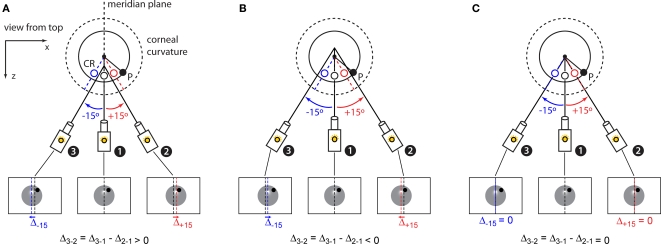
Figure 5.
Estimation of the 3D center of the corneal curvature. (A) At the end of the previous calibration steps (see Figure 4), the camera is in position 1, i.e., with the eye centered on the camera's sensor. Motorized stages allow pseudo-rotations of the camera about a distant point along its optic axis (solid lines) by combining a horizontal translation with a rotation (see Figure 1C). If such a rotation happens about a point in front of the center of the corneal curvature the corneal reflection (CR) produced by the horizontally aligned (top) infrared LED will appear offset (red and blue open circles) of its location at the camera's starting point (black empty circle). Specifically, positive (counter-clockwise from the top, red) and negative (clockwise, blue) pseudo-rotations result in a rightward and leftward displacements of the CR respectively. Therefore, the difference (Δ3-2) between the displacement of the CR produced by the positive (red arrow) and negative (blue arrow) camera rotations will be positive. (B) When the camera is rotated about a virtual point (along its optic axis) behind the center of the corneal curvature the CR will be displaced medially and Δ3-2 will be negative. (C) If the camera rotates about a virtual point that is aligned to the center of the corneal curvature both the right (red arrow) and left (blue arrow) 15° rotations will produce no displacement of the CR and Δ3-2 will be null.

