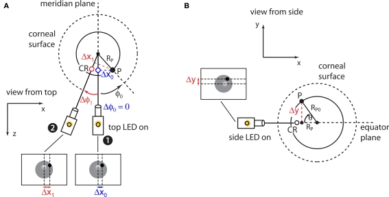
Figure 6.
Estimation of the radius of pupil rotation. (A) At the end of the previous calibration steps (see Figures 4 and 5) the camera is in position 1, i.e., its sensor and the eye are aligned and the camera can be rotated about the center of the eye (small black circle). Additionally, illumination from the horizontally aligned (top) infrared LED results in a corneal reflection (CR; blue circle) that marks the meridian plane of the eye. Generally, the pupil (P; black circle) will not be aligned with the eye's meridian plane (i.e., it will not point straight to the camera). This displacement can be described as an initial angle ɸ0 (black arrow) between the eye's meridian plane and RP (the projection of the radius of rotation of the pupil RP0 on the eye's equator plane; see also Figure 3) and an initial distance Δx0 between the pupil and the eye's meridian plane. When the camera is rotated to an angle Δɸ1 about the center of the eye (red arrow), the distance Δx1 between the pupil and the eye's meridian plane will depend on both Δɸ1 and the pupil initial angle ɸ0 (see Eq. 3 in Methods). (B). Once RP is known by the fit to Eq. 3 (see Materials and Methods), RP0 can be easily obtained by switching on the vertically aligned (side) infrared LED and measuring the distance Δy of the pupil from the eye's equator plane (marked by the resulting CR spot; empty circle). In general, such a distance will not be null due to an initial elevation θ (black arrow) of the pupil from the equator plane.

