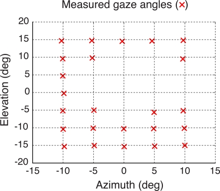
Figure 7.
Validation of the eye-tracking system using an artificial eye. The artificial eye was rotated to a grid of known azimuth and elevation angles (intersections of the dashed lines) while the pupil on its surface was tracked. Pupil gaze measurements were repeated 10 times and their average values were drawn (red crosses) superimposed over the grid of know gaze angles to show the accuracy of the eye-tracking system. Missing measurements (i.e., grid intersections with no red crosses) refer to pupil rotations that brought the LED infrared source to shine directly onto the opaque simulated pupil, resulting in a missing CR spot (see Materials and Methods).

