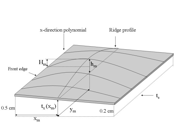
Figure 7.

The correction model. All relevant measured distances, positions, ridge-profile, and separable x-direction polynomials are labeled on this correction surface illustration. The dashed line represents system thickness readout plane with ts (system readout height) parallel to the breast support surface. The ridge-profile runs along the y-direction at × = xm with a maximum height hm located at (xm, ym) measured above the perimeter height at xm. Hm is the height above ts +0.5 cm measured from H(x, y) that was used to derive hm. A given x-direction polynomial was constructed with the position and height of the ridge-profile at the intersection of the two polynomials along with the relative paddle parameter heights at × = 0 and × = xmax, which are 0.5 cm and 0.2 cm, respectively.
