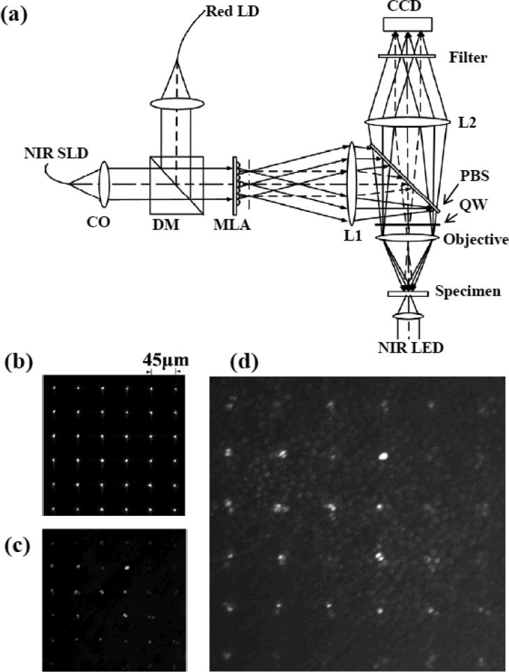
Fig.1.
(a) Schematic diagram of the MLA recording system: CO, collimator; DM, dichroic mirror; MLA, microlens array; PBS, polarization-sensitive beam splitter; QW, quarter-wave plate. Focal lengths of the lenses L1 and L2 are 80 and 150 mm, respectively. NIR SLD was used for IOS imaging. Red laser diode (LD) was used for retinal stimulation. NIR LED was used for transmission imaging of the retina. At the dichroic mirror (DM), collimated NIR recording light and visible stimulus light were combined together to illuminate microlens array (MLA) simultaneously. (b) Representative MLA pattern by placing a mirror at the specimen plane. (c) Representative MLA imaging pattern of an isolated frog retina. (d) Simultaneous MLA recording and transmission imaging of the retina.

