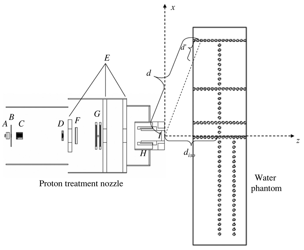
Figure 1.
Schematic illustration of the PSPT treatment nozzle and the water phantom. The nozzle includes a vacuum window (A), a beam profile monitor (B), a range modulator wheel (C), a second scatter (D), shielding plates (E), a range shifter assembly (F), backup and primary monitors (G), the snout (H) and the final aperture (I). Neutron dose was calculated in 2 cm diameter spherical receptors (open circles) in both axial (z) and lateral (x) directions. In the figure, d indicates the distance from the effective neutron source to the neutron receptor, d′ indicates the distance from the phantom surface to the neutron receptor along the path between the effective neutron source and the receptor, diso indicates the distance from the effective neutron source to the isocenter. The figure is not drawn to scale.

