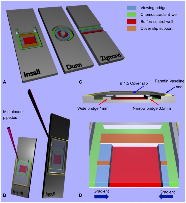
Figure 1. Comparison of bridge chamber features.
(A) Schematic showing the Insall, Dunn and Zigmond chambers. The chemoattractant and buffer/control wells have been colour coded for direct comparison, along with the viewing bridges and cover slip supports. Note that the central cylindrical block on the Dunn chamber is the same height as the bridge and therefore offers no support to the cover slip. Fig 1 (B) demonstrates the versatility of the chamber with front or reverse side chemoattractant loading with no requirement for metal clips, unlike the Zigmond chamber. The latter technique involves loading after the cover slip has been secured and sealed in place with a 1∶1 mix of vaseline: paraffin, producing a tight seal that reduces the risk of evaporation during experiments over several hours. Fig 1 (C) Cross section through the Insall chamber highlighting one key feature – the ability to use thin (#1.5, 0.16–0.18 mm) cover slips that permit high NA oil immersion microscopy. Bridges of differing widths provide different gradient steepnesses. Fig (D) provides a close-up of the Insall chamber and demonstrates the directions of the two chemotactic gradients, which are unidirectional across each bridge.

