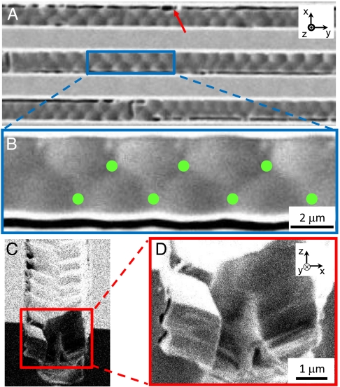
Fig. 3.
SEM images of confined B7 phase in 5 μm wide channels. (A) SEM shows topographical pattern with the same periodicity as found in the DRLM investigation Fig. 2C. (B) The magnified image of A shows what appears to be an array of truncated spherulitic domains in contact to form a periodic lattice along the channel. The green dots are the low points on the surface and the meeting points of three truncated spherulitic domains. (C and D) Cross-sectioned structure of one channel shows a preference for smectic layers to be normal to the channel surface. The dark lines (red arrow) are cracks appearing upon quenching of the sample for SEM, i.e., artefacts of the SEM sample preparation. The channel width (w), depth (d), and separation is 5 μm.

