Fig. 4.
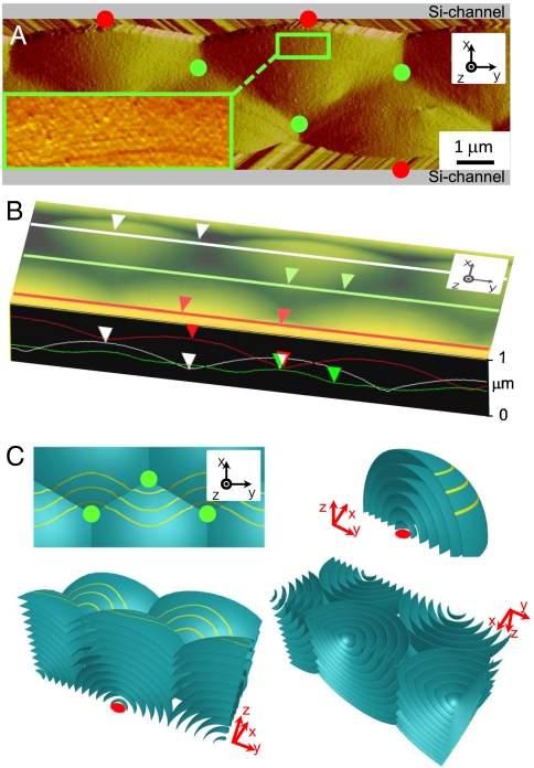
AFM micrograph and structural scheme of the channel confined B7 phase. (A) The long wavelength optical layer and undulation of Figs. 2 and 3 is visible, as well as the linear layering ripples of the polarization splay modulation. A red circle indicates the nucleation point of each domain. (B) Height mode AFM image shows the surface profile pattern clearly, with height difference of 300 nm between the high and low points. (C) Sketch of the proposed internal smectic layering structure generating the surface profile of B, consisting of a periodic array of spherulitic smectic focal conic domains that nucleate at the bottom corners of the channel, grow, and intersect. The top view shows the intersections of these domains and connection lines as found in SEM and AFM images. Three dimensional views from top and bottom of confined B7 phase show how these focal conic domains form in-channel. Yellow lines in top view are modulation lines of B7.

