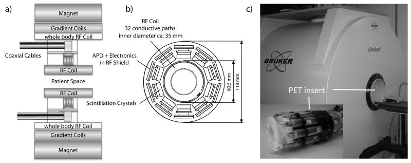
FIG. 1.
a) The schematic structure of the MR system with the built-in PET insert. The PET insert is installed inside the magnet bore. For PET/MR experiments, a transmit/receive RF coil installed inside the PET insert is used. The whole body coil of the MR system is muted for the PET/MR experiments. This design allows an easy transformation from an MR only system to a PET/MR system by just installing the PET insert inside the magnet. b) A CT image of the RF coil used in this study is superimposed on a schematic view of the 10 PET detectors of the PET insert. The coil has 32 conductive paths, which are symmetrically positioned with respect to the PET detectors. Therefore, a symmetric γ-radiation attenuation effect caused by the RF coil can be expected. However, when surface or local RF coils are used, asymmetric γ-radiation attenuation effects have to be expected. In general, the attenuation caused by the RF coil is an important parameter for PET/MR imaging. c) Photograph of the 7 T, small animal MR scanner as well as the PET insert that is installed at the center of the MR field of view.

