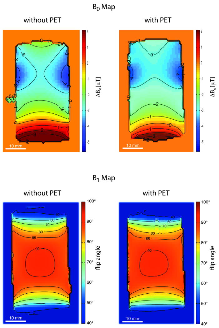
FIG. 2.
a) B0 field mapping. The main static magnetic field homogeneity is shown by a coronal slice obtained with a phantom placed at the center of the PET/MR FOV. In both cases, without (left) and with (right) the PET insert installed into the MR, a relative homogenous region is found in the frontal part of the phantom (top of the images). The back of the phantom (bottom of the images) features a change in the main magnetic field from -1 μT to +2 μT. Susceptibility effects induced by the fluid, plastics and especially by phantom cap interfaces cause these changes. b) B1 field homogeneity. Flip angle distribution in a coronal slice obtained without (left) and with (right) the PET insert installed. No fundamental alteration of the B1 field was observed when the measurements for the two configurations were compared. Small differences in the B1 field between the two configurations might partly be caused by tolerances in slice positioning.

