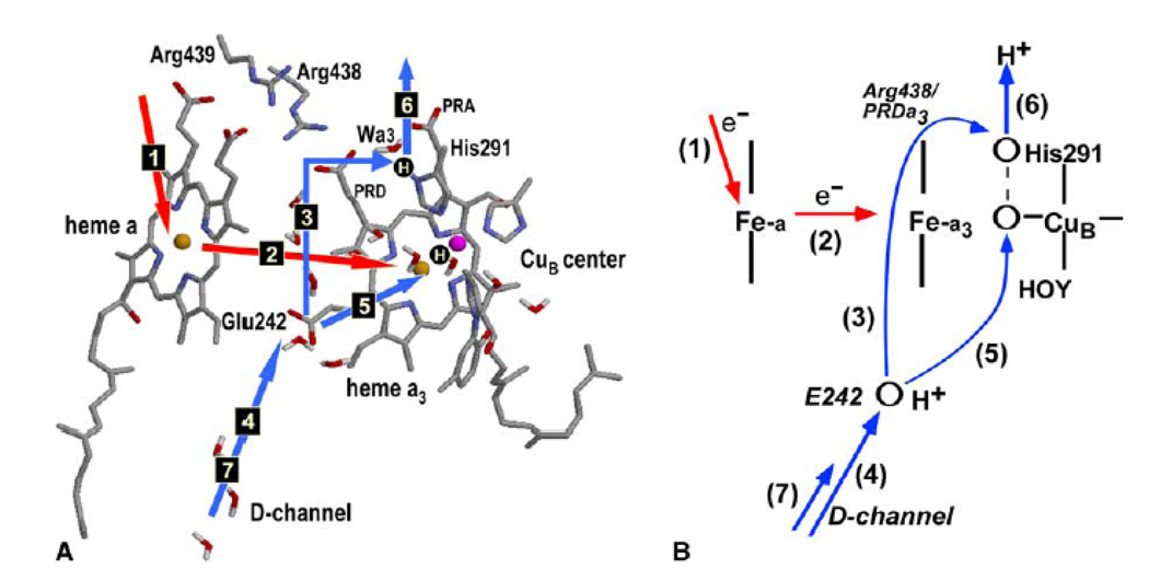
Fig. 12.
(A) The key structural elements of the proposed pumping mechanism of CcO and the sequence of transitions during one pumping cycle. Two protonation sites, the PLS and a site in the BNC, are shown as H-circles. PT and ET steps are shown by blue and red arrows, respectively. The residue notation is for bovine enzyme. (B) Schematic depiction of the model. The key assumption of the model is that upon ET between the hemes (step 2), the proton transfer to the Proton Loading Site (step 3) occurs before the proton transfer to the BNC (step 5). Figure reprinted with permission from Ref. 159. Copyright 2004 Elsevier.

