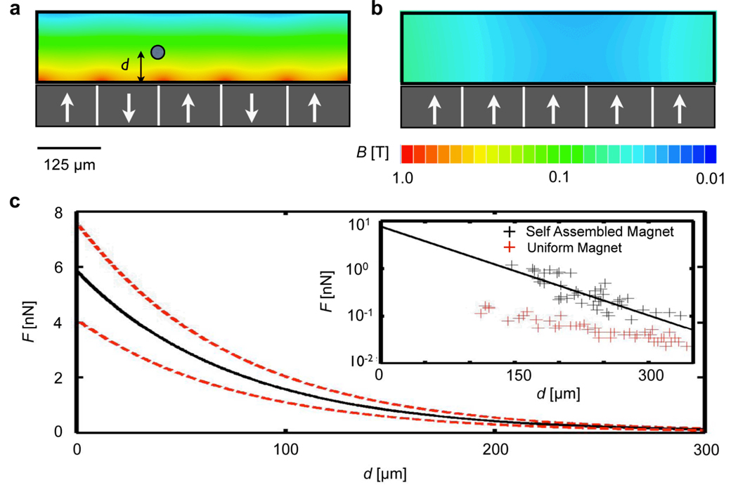
Figure 2.
Characterizing the self assembled magnet filter. (a) Magnetic field simulations. The magnetic field is plotted on the cross section of the microfluidic channel for an ideal system of anti-aligned magnetic dipoles. White arrows represent the dipole direction. (b) For comparison, the magnetic field is also plotted for a system in which all of the poles are uniformly aligned. The |B| from (a) decays much faster than in (b), resulting in much greater magnetic forces for the case of anti-aligned dipoles. (c) The inset shows the experimentally measured force on magnetic beads (Dynabead MyOne; Invitrogen) as a function of their distance from a self assembled magnet (black) and a uniformly magnetized magnet (red). The force measured on the self-assembled magnet has a magnitude of several nN and fits well to an exponentially decay function, plotted (black) with upper and lower bounds (dotted lines in red) vs. d.

