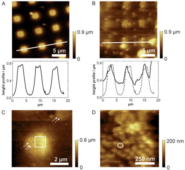
Figure 2.

NE attached on CellTAK modified PDMS microstructures. A) Overview scan of bare PDMS in contact mode in dry state. The image reveals flat and regular arrangements of the plateaus. Below the cross-section along the white line. B) Overview scan image of the membrane preparation performed in contact mode. The less height differences and the cloudy appearance indicate a patch of NE. Below the cross-section along the white line (solid line). The dashed line denotes the profile of bare PDMS. The comparison of these two section analysis indicates the stable immobilization of the NE membrane on micro-structured PDMS. C) The small spots appearing in the image can be identified as NPCs (highlighted with arrows). The image demonstrates that the NE is stably spanned over the wells. The square indicates the scan area of Figure 2 D. D) A dense layer of NPCs embedded in the membrane is observed. A single NPC is framed with a white circle.
