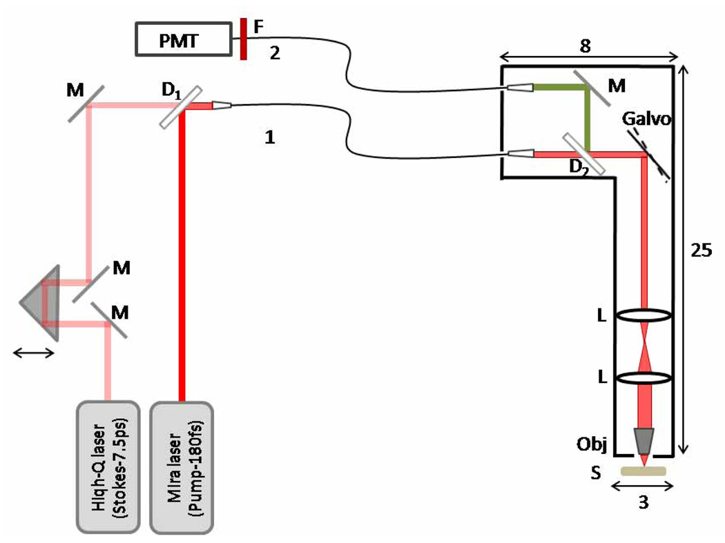
Fig. 1.
Schematic diagram of the fiber-delivered probe for CARS tissue imaging: M-mirrors; D1- 1000 nm longpass dichroic mirror; D2- 760 nm longpass dichroic mirror, L-lens; Obj-objective; S-sample; F- 670 nm bandpass filter. Fiber 1 is used for delivery of the excitation pulses and fiber 2 is used for detecting the CARS radiation. The dimensions of the probe are indicated in cm.

