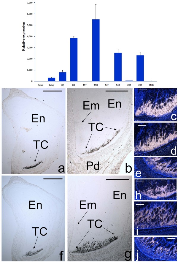
Figure 2.
Expression analysis of ZmTCRR-2. Upper panel, the graph represents the accumulation of the transcript along early development, relative to its level in the first time point tested (3 DAP). Numbers in the X-axis indicate days after pollination, EMB indicates embryo at 20 DAP, T and B indicate top (upper) and bottom (lower) half of the seed, respectively. Lower panel, Comparison of transcript accumulation sites of ZmTCRR-1(a to e) and ZmTCRR-2 (f to J) at 6 (c, h), 10 (a, b, d, f, g, i) and 14 (e, j) days after development, covering the transfer cells differentiation period. Images in a, b, f and g were taken in bright field using 1.25× (a, f) and 2.5 × (b, g) objectives. The condenser diaphragm was closed to increase contrast and visualize the unstained tissue. The hybridisation signal appears as a layer of black spots in the transfer cells. Images in c, d, e, h, i and j are dark field images, the signal is shown as white dots. Sections were counterstained with Calcofluor White to show the tissue structure. En, inner endosperm; Em, embryo; TC, transfer cells; Pd, pedicel. Scale bars represent 1 mm in a, b, f and g and 100 μm in c, d, e, h, i and j.

