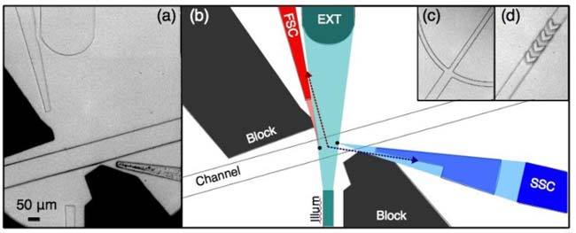
Fig. 1.

(a) Microscope image of the microfluidic device. (b) Scale schematic of device showing light scatter (‘FSC’ and ‘SSC’) collected by waveguides from interrogation centers (two black circles in channel). Note that light originating from between these centers is incident on an angled facet (see arrows), resulting in large reflection or refraction losses. After traversing the fluidic channel, the illumination beam is guided off the chip by the beam dump, which by nature will collect the ‘extinction’ signal (EXT), a dip in intensity as samples pass. c) Typical fork-style lateral hydrodynamic focusing and (d) chevron-based vertical focusing are used to confine sample flow.
