Figure 1.
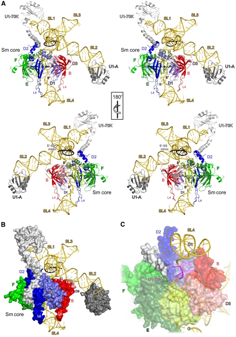
Overall structure of U1 snRNP. (A) Orthogonal stereo ribbon plots of native U1 snRNP. snRNA, gold; DNA nonamer mimicking a 5′-SS, black; U1-70K, light grey; U1-A, dark grey; D1, steel blue; D2, blue; F, green; E, dark green; G, lime; D3, light red; B, red. SLs and termini of the RNA and the long L4 loops of D2 and B are labelled. (B) Native U1 snRNP with the proteins shown in surface representation. The Sm proteins provide a platform for the four-way junction and 5′-SS-binding region. U1 proteins package the central region of the snRNA and the tips of SL1 and SL2, but leave the core of the cruciform, the 5′-SS-binding region, SL3 and the tip of SL4 open. These RNA regions may provide docking sites for other spliceosomal factors. The view is the same as in panel A. (C) Contacts between the N-terminal extension of the U1-70K protein (light grey surface) at the underside of the Sm ring (semitransparent surfaces) and U1 snRNA (gold) in the region of residues A135 and G136 (magenta). Rotated 135° about the x axis compared with panel A.

